Assembly of interior frame walls
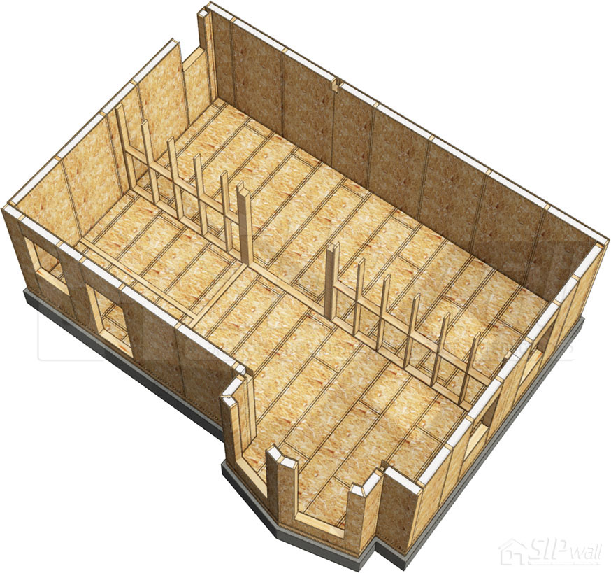
Assembly of interior load-bearing frame walls on floor 1
Load-bearing frame walls are made of 37 × 147 mm boards. The bottom plate board of the interior load-bearing frame wall is fixed to the floor with 4,2 × 64 mm screws, 2 pcs. into each built-in floor joist, according to the floor plan. Next, posts of 37 × 147 mm are fixed to the plate board with 6 × 80 mm screws (3 pcs. per joint) at the spacing specified in the design. The spacing is calculated taking into account the subsequent cladding of the frame walls. Double posts are provided at the edges of the frame module. The T-joint of the load-bearing interior frame wall with the exterior walls is drawn together with JD plus 8 × 240 mm screws or equivalents at 400 mm spacing. After all posts are installed, a single or double top plate, according to the design, is fixed on top with 6 × 80 mm screws, 3 pcs. per post. If there is a post for a beam inside the frame module, it is built up on site with 4,2 × 64 mm screws in a staggered pattern at 150 mm spacing and fixed to the bottom plate board with reinforced brackets and 6 × 80 mm screws (10 pcs. per bracket). At a height of 1200–1500 mm above the bottom plate, wooden lintels are fixed between the posts with 4,2 × 64 mm screws (4 screws per lintel). For the main structural details, see Appendix No. 2. Album of Technical Solutions – SIP Panel Structural Details: Joints of SIP Wall Panels and Frame Walls.
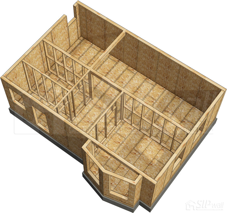
Assembly of interior non-load-bearing frame walls on floor 1
Non-load-bearing walls are made of 37 × 97 mm boards. The bottom plate board of the interior non-load-bearing frame wall is fixed to the floor with 4,2 × 64 mm screws in a staggered pattern at 250 mm spacing, according to the floor plan. Next, posts of 37 × 97 mm are fixed to the plate board with 4,2 × 64 mm screws (3 pcs. per joint) at the spacing specified in the design. The spacing is calculated taking into account the subsequent cladding of the frame walls by the client. The outer posts of the module are fixed to the perpendicular module with 4,2 × 64 mm screws at 250 mm spacing. After all posts are installed, a top plate is fixed on top with 4,2 × 64 mm screws (3 pcs. per post). Between the posts, wooden lintels are fixed at a height of 1200–1500 mm above the bottom plate with 4,2 × 64 mm screws (4 pcs. per lintel) if the module is higher than 3000 mm. For the main structural details, see Appendix No. 2. Album of Technical Solutions – SIP Panel Structural Details: Joints of SIP Wall Panels and Frame Walls.
Before proceeding to the next stage of construction, the installation of the structure must be inspected in accordance with technical supervision (Appendix No. 1. Technical Supervision of the Construction of a SIP Panel House Using SIPwall Technology).
Book contents