Assembling the intermediate floor
Assembling the intermediate floor from SIP panels
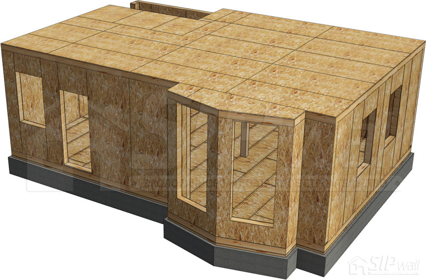
The next stage of construction is assembling the intermediate floor panels. Assembly follows the floor panel layout diagram. The panels are laid out along the side of the house and spliced along their length by inserting the tongue of one panel into the groove of another, filled beforehand with assembly foam, and fixing them with screws 3,5 × 41 mm. Once the length is made up, a timber joist is built into the assembled panels, either of solid timber 74 × 147 mm or built up from boards 37 × 197 mm. Before the joist is built in, all grooves and surfaces of the elements to be joined (built-up joists) are foamed with assembly foam. The foam is applied in a zigzag or around the perimeter of the panel groove or of the element being joined. When the floor panels are assembled, the “plate board” is built into the panel around the perimeter, the groove for the strapping having been foamed beforehand. Then the “from below” is fixed on and underneath through the OSB with wood screws 3,5 × 41 mm at a spacing of 150 mm. For the main structural details, see Appendix No. 2. Technical Solutions Album – SIP panel details: Intermediate and attic floors.
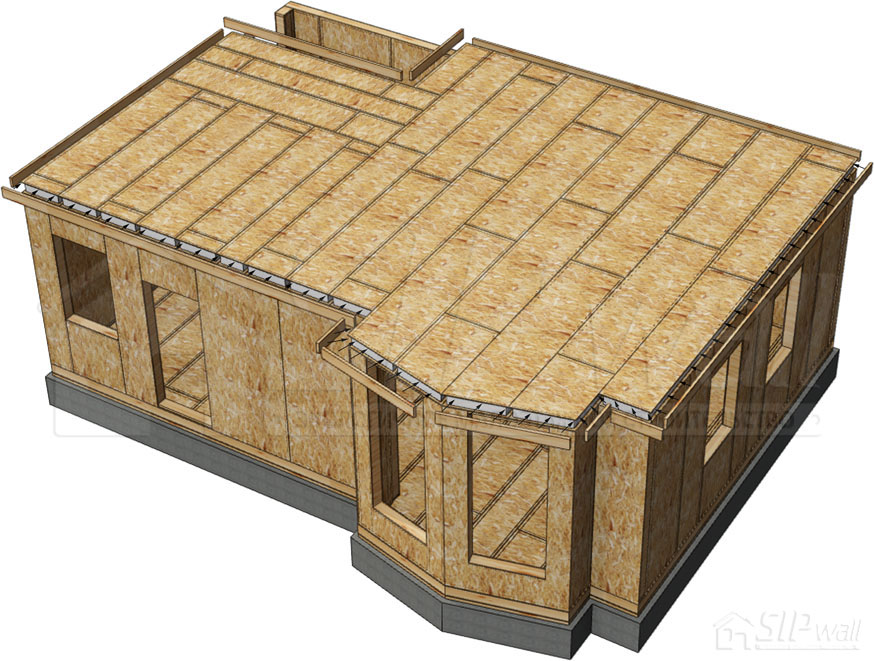
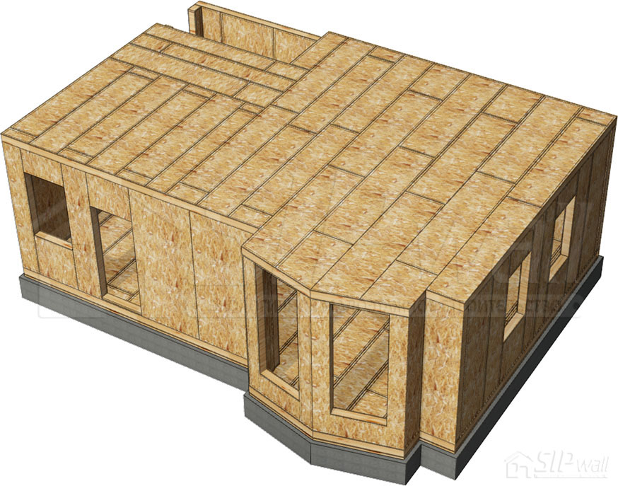
Assembling a frame intermediate floor from I-joists
Assembly of the frame intermediate floor from I-joists follows the joist layout diagram. Single-piece joists may be up to 7,4 m long. I-joists are fixed at their supports to the top strapping board of the walls, or to beams, with nails 3 × 70 mm (2 pcs. per detail). I-joist blocking is installed to stiffen the structure and fixed with nails 3 × 70 mm – 2 pcs. into the top strapping of the walls and 2 pcs. into the I-joist perpendicular to it. For the main structural details, see Appendix No. 4. Technical Solutions Album – SIPwall timber I-joists for floors.
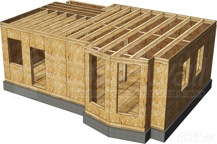
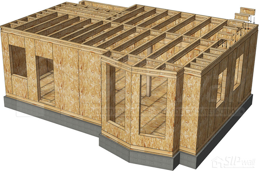
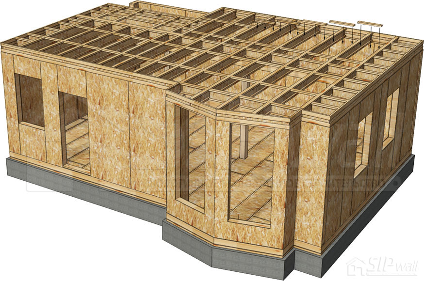
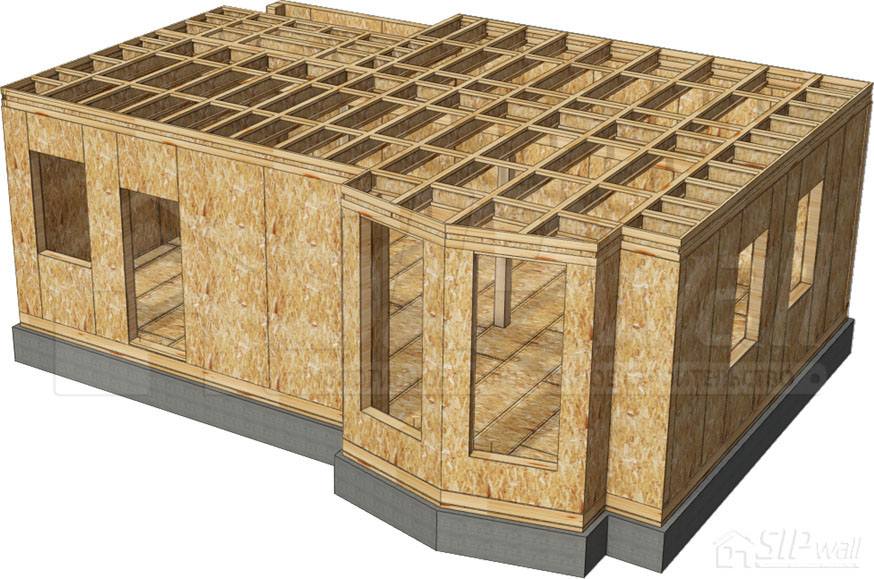
To fix OSB decking 22 mm, a board 37 × 97 mm must be fixed to the top flange of the joists under the sheet joints with nails 3 × 70 mm (4 pcs. per block). For joist reinforcement and complex details, see Appendix No. 4. Technical Solutions Album – SIPwall timber I-joists for floors.
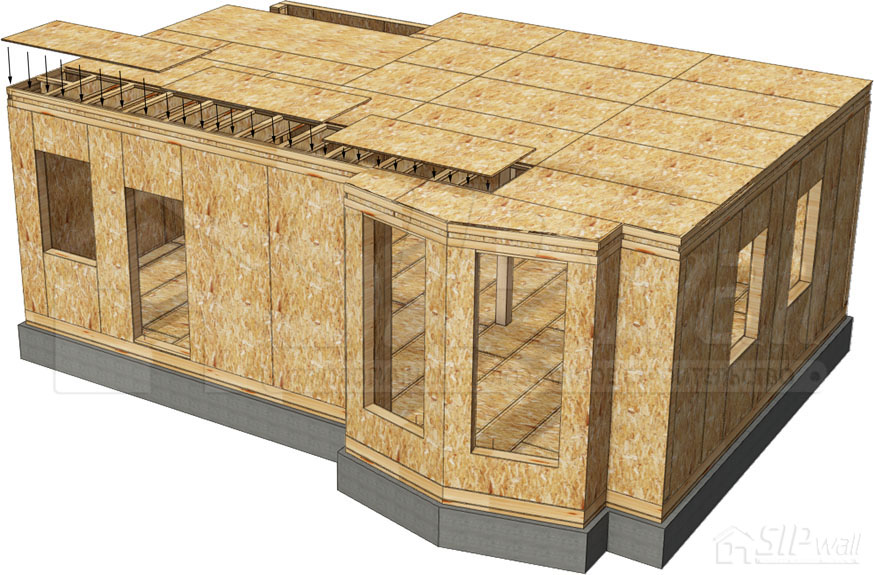
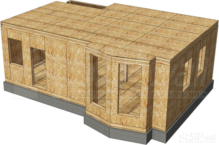
Before proceeding to the next stage of construction, the installation of the structure must be inspected in accordance with technical supervision (Appendix No. 1. Technical Supervision of the Construction of a SIP Panel House Using SIPwall Technology).
Assembling a frame intermediate floor
Assembly of the frame intermediate floor follows the floor joist layout diagram. The joists may be either of solid timber 74 × 147 mm or built up from boards 37 × 197 mm (the boards are fixed together with screws 4,2 × 64 mm at a spacing of 150 mm in a staggered pattern). The joists are laid out along the side of the house and spliced along their length, strictly over a support, with metal plates 100 × 300 mm and screws 3,5 × 41 mm. Joists are fixed to their supports with screws 6 × 80 mm, 3 pcs. per detail. The “plate board” is fixed on around the perimeter. For the main structural details, see Appendix No. 2. Technical Solutions Album – SIP panel details: Intermediate and attic floors.
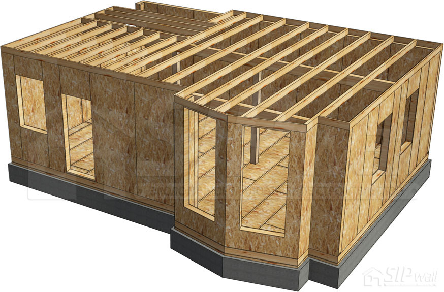
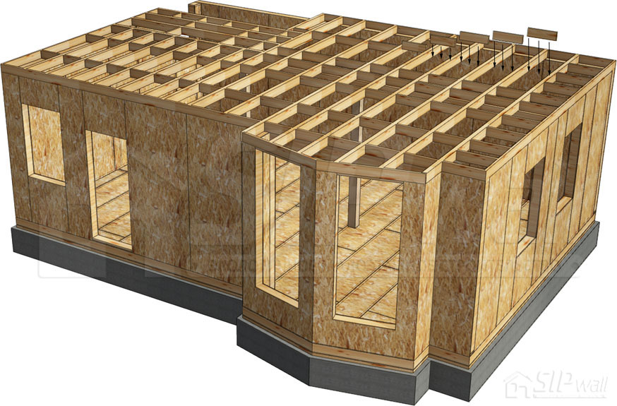
Blocking between joists is installed at the joints of the OSB covering and for stiffness as per the design.
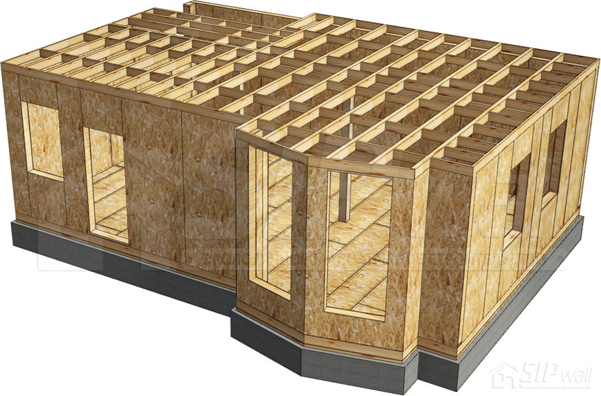
The OSB decking is fixed with screws 3,5 × 41 mm at a spacing of 150 mm.
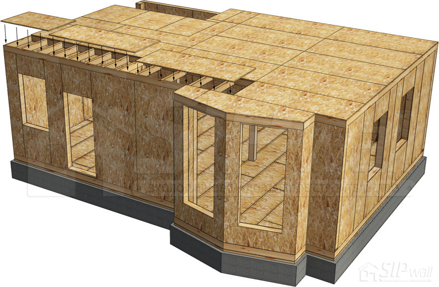
Before proceeding to the next stage of construction, the installation of the structure must be inspected in accordance with technical supervision (Appendix No. 1. Technical Supervision of the Construction of a SIP Panel House Using SIPwall Technology).
Book contents