Installing floor panels at level 0,000
Assembly of floor panels with built-in timber
After the panels are joined lengthwise, a timber – a joist – is built into the assembled panels. The joist may be made of dry planed solid timber of 74 × 147 mm or built up from dry planed boards of 37 × 197 mm. Before the beam is built in, all grooves and the surfaces of the elements being joined (built-up beams) are filled with mounting foam. The foam is applied either in a zigzag pattern or around the perimeter of the panel groove or the perimeter of the element being joined.
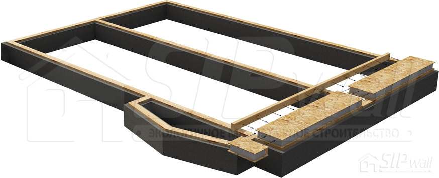
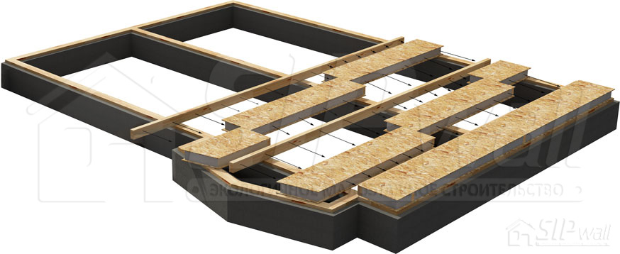
For the main structural details, see Appendix No. 2. Album of Technical Solutions – SIP Panel Structural Details: Installing Floor Panels at Level 0,000.
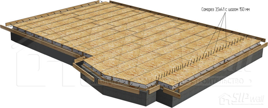
When the floor panels have been assembled, “plate board” is built into the panel around the perimeter, with the plate groove filled with foam beforehand. It is then nailed and fixed through the OSB with 3,5 × 41 mm wood screws at 150 mm spacing.
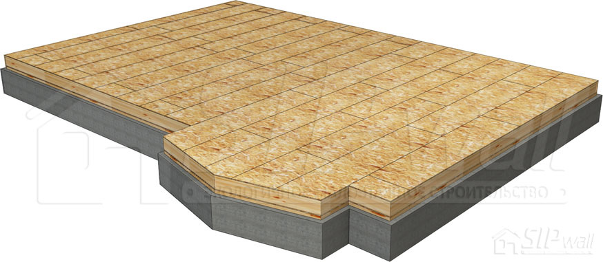
The floor is fixed to the timber grillage or plate board with JD plus screws or equivalents, driven through the bottom plate board of the load-bearing walls of floor 1 at the locations of the built-in floor joists: every second joist if the panels are reinforced (620 × 2800 mm), and every built-in joist if the panels are not reinforced (1250 × 2800 mm), as well as along the long side at 1250 mm spacing (screw length depends on the floor thickness). The bottom plate board of the wall panels is placed at a distance of one panel thickness, 12 mm, from the edge of the floor, and the contact plane between the plate and the floor must be filled with foam. For detailed floor fixing details, see “Appendix No. 2. Album of Technical Solutions – SIP Panel Structural Details”.
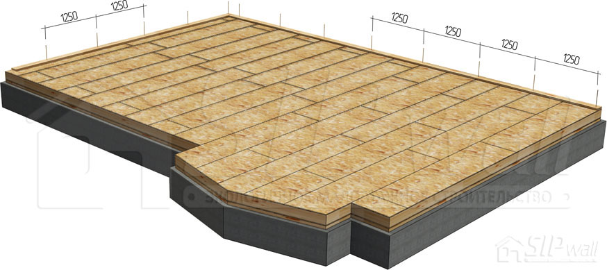
- Fixing to the timber grillage with screws:
- Floor panel 174 mm thick — JD plus screws 280 mm or equivalents
- Floor panel 224 mm thick — JD plus screws 320 mm or equivalents
- Fixing to the plate board with screws:
- Floor panel 174 mm thick — JD plus screws 240 mm or equivalents
- Floor panel 224 mm thick — JD plus screws 300 mm or equivalents
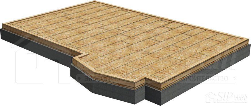
Before proceeding to the next stage of construction, the installation of the structure must be inspected in accordance with technical supervision (“Appendix No. 1. Technical Supervision of the Construction of a SIP Panel House Using SIPwall Technology”).
Assembly of floor panels with I-beams
The floor is assembled according to the layout of the floor panels, either along or across the axis of the house.
The panels are laid out along the wall of the house and joined lengthwise by inserting the tongue of one panel into the groove of the other, treated with mounting foam, and fixing them with 3,5 × 41 mm screws. After the panels are joined lengthwise, an I-beam – a joist – is built into the assembled panels. The places shown in figures 16 and 17 are filled with mounting foam.
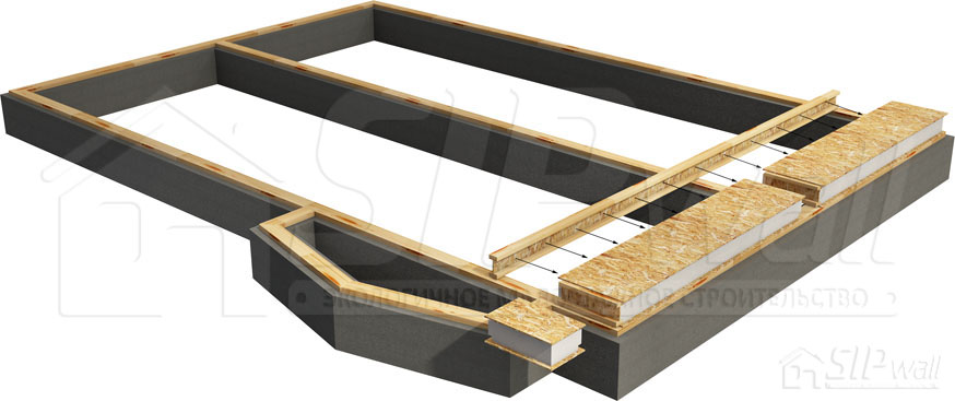
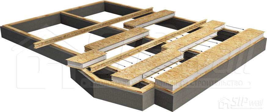
For the main structural details, see “Appendix No. 2. Album of Technical Solutions – SIP Panel Structural Details: Installing Floor Panels at Level 0,000”.
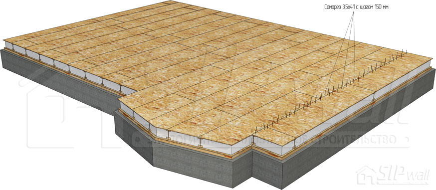
When the floor panels have been assembled, “plate board” is built into the panel around the perimeter, with the plate groove filled with foam beforehand. It is then nailed and fixed through the OSB with 3,5 × 41 mm wood screws at 150 mm spacing. For the main structural details, see “Appendix No. 2. Album of Technical Solutions – SIP Panel Structural Details: Installing Floor Panels at Level 0,000”.
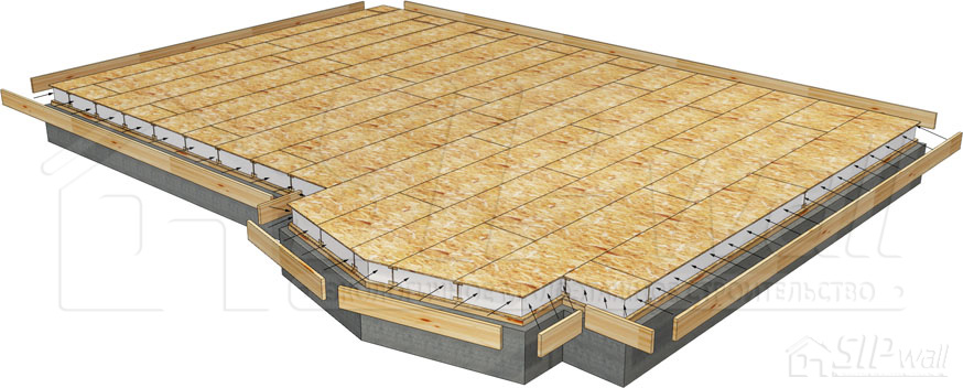
Fixing is done with JD plus screws or equivalents through the bottom plate board of the load-bearing walls of floor 1 at 1250 mm spacing (screw length depends on the floor thickness), but not through the I-beams. The bottom plate board of the wall panels is placed at a distance of one panel thickness, 12 mm, from the edge of the floor, and the contact plane between the plate and the floor is filled with foam. SIP panels with I-beams are reinforced according to the project drawings; the design may allow replacing elements with a 37 × 197 mm board. Where the beams bear on the exterior walls, the beams are reinforced with a 37 × 97 mm board between the upper and lower flanges (see “Appendix No. 2. Album of Technical Solutions – SIP Panel Structural Details”).
- Fixing to the timber grillage with screws:
- Floor panel 174 mm thick — JD plus screws 280 mm or equivalents
- Floor panel 224 mm thick — JD plus screws 320 mm or equivalents
- Fixing to the plate board with screws:
- Floor panel 174 mm thick — JD plus screws 240 mm or equivalents
- Floor panel 224 mm thick — JD plus screws 300 mm or equivalents
Before proceeding to the next stage of construction, the installation of the structure must be inspected in accordance with technical supervision (Appendix No. 1. Technical Supervision of the Construction of a SIP Panel House Using SIPwall Technology).
Book contents