Installing the timber grillage on foundations
Installing the strapping board on the reinforced concrete foundation strip
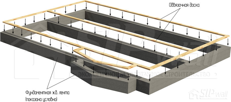
Figure 1. The strapping board – the top part of the foundation, made of a board 40 × 150 mm or (50 × 150 mm) – transfers loads to the foundation and also serves as the base for fixing the floor at level 0.000 m. It is laid through 2 layers of roll waterproofing and fixed with an anchor bolt at a spacing of 1 m.
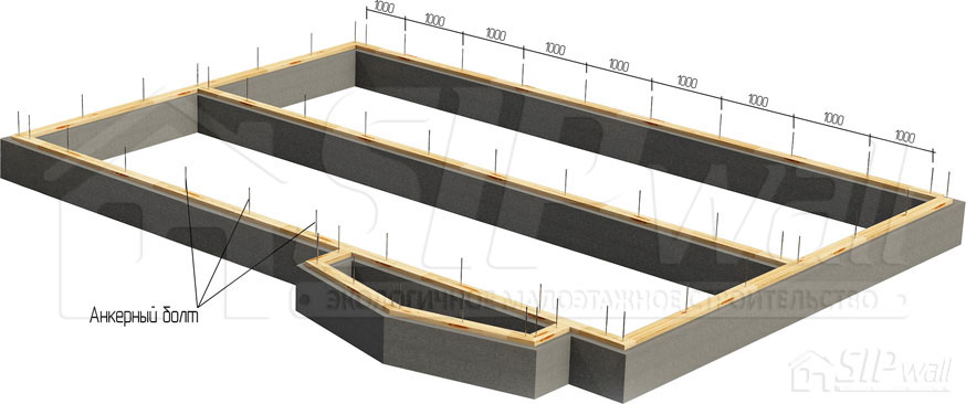
Figure 2. The strapping board is fixed to the foundation with an anchor bolt 12 × 110 mm, at a spacing of 1 m, through 2 layers of roll waterproofing. Before proceeding to the next stage of construction, the installation of the structure must be checked in line with technical supervision (Appendix No. 1. Technical supervision of the construction of a SIP panel house using SIPwall technology).
Installing the timber grillage on reinforced concrete piles
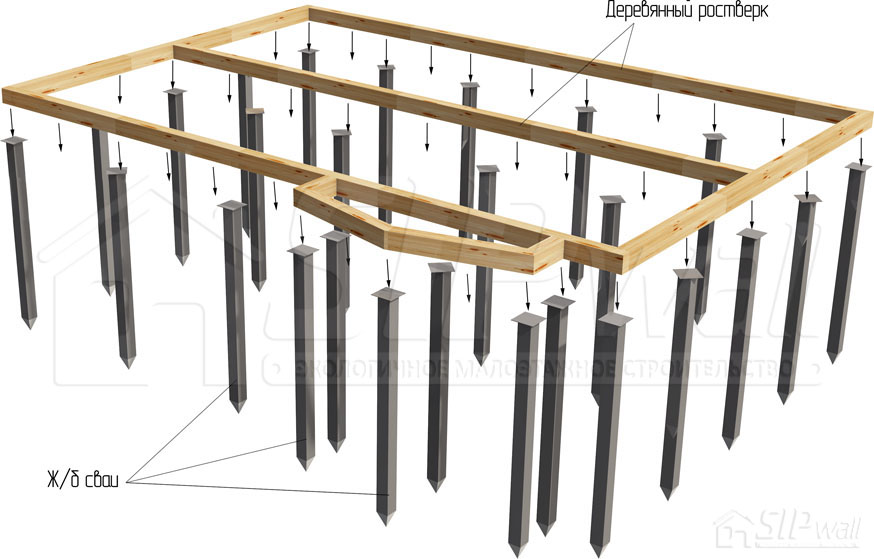
Figure 3. The timber grillage is the top part of a pile or column foundation that distributes the load to the base. The timber grillage is made as beams of boards fixed together, joining the heads of the columns (piles) and serving as the supporting structure for the building elements. Splice the grillage along its length strictly over pile heads; only one board may be spliced away from a pile head. If the grillage is made of lumber at natural moisture content, the boards are fixed together with screws 90 mm from both sides in a staggered pattern at a spacing of 250 mm. It is then tied along its length with a threaded rod at an interval of 1,2 m. If the grillage is made of dry lumber, the boards are fixed together with screws 64 mm from three sides in a staggered pattern at a spacing of 250 mm. It is then tied along its length with a threaded rod at an interval of 1,2 m. Installation is carried out with a leveling instrument or a spirit level. The timber grillage is fixed to the reinforced concrete piles with threaded rods or lag screws M10 through a metal plate welded to the pile head, through 2 layers of roll waterproofing. The grillage may also be fixed to the pile heads with threaded rods through 2 layers of roll waterproofing, as on screw piles. The choice of method depends on the pile section and the head size.
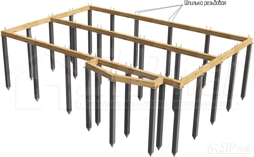
Figure 4.
Installing the timber grillage on screw piles
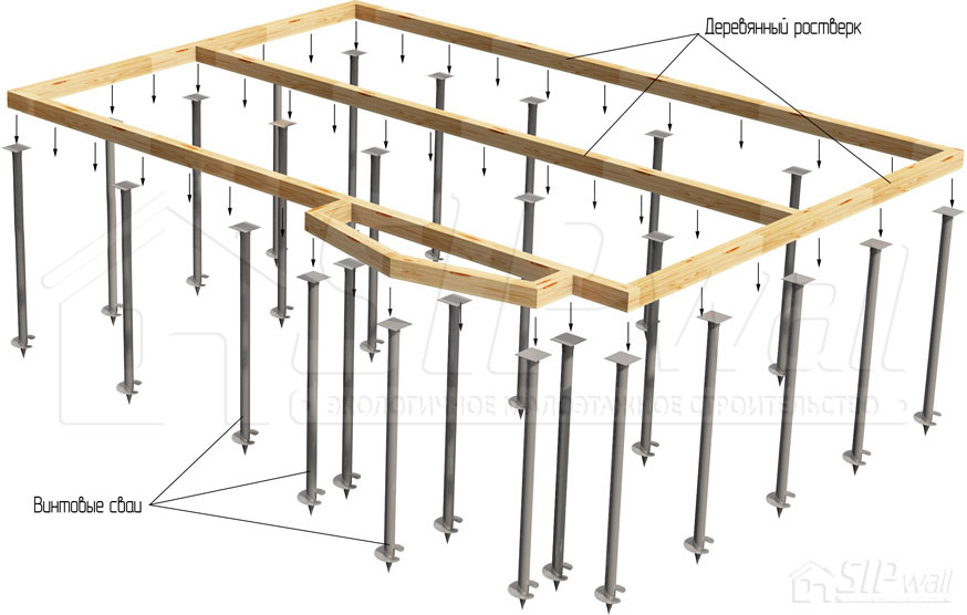
Figure 5. Splice the grillage along its length strictly over pile heads; only one board may be spliced away from a pile head. If the grillage is made of lumber at natural moisture content, the boards are fixed together with 90 screws from both sides in a staggered pattern at a spacing of 250 mm. If the grillage is made of dry lumber, the boards are fixed together with 64 screws from three sides in a staggered pattern at a spacing of 250 mm. It is then tied along its length with a threaded rod at an interval of 1,2 m. The timber grillage is installed with a leveling instrument or a spirit level. The timber grillage is fixed to the pile heads with threaded rods or lag screws M10 through 2 layers of roll waterproofing.
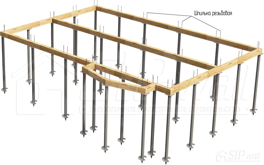
Figure 6.
Installing the strapping board on a channel
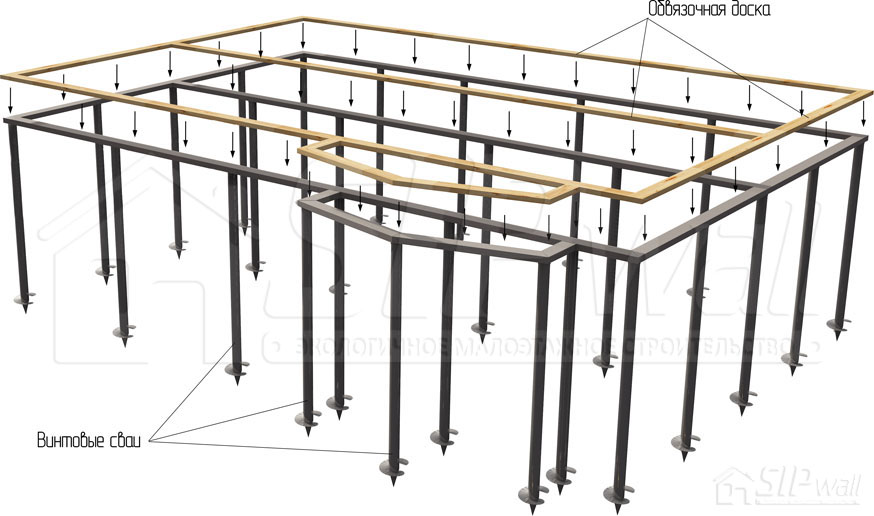
Figure 7. The channel for the grillage is selected by calculation. The minimum dimensions of the channel used in this position are 140 mm (channel 14); the offset of the channel's and pile's center axis from the main axis is 5 mm (see Appendix No. 2. Technical Solutions Album – SIP panel details).
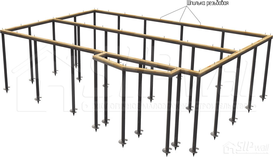
Figure 8. The strapping board is installed on the channel with a leveling instrument or a spirit level. The strapping board is fixed to the channel with a threaded rod or lag screw M10 at a spacing of 1,2 m through 2 layers of roll waterproofing. For the main structural details, see Appendix No. 2. Technical Solutions Album – SIP panel details: Grillage on foundations. Before proceeding to the next stage of construction, the installation of the structure must be checked in line with technical supervision (Appendix No. 1. Technical supervision of the construction of a SIP panel house using SIPwall technology).
Book contents