Roof installation
Installing a roof from SIP panels
Installing roof panels
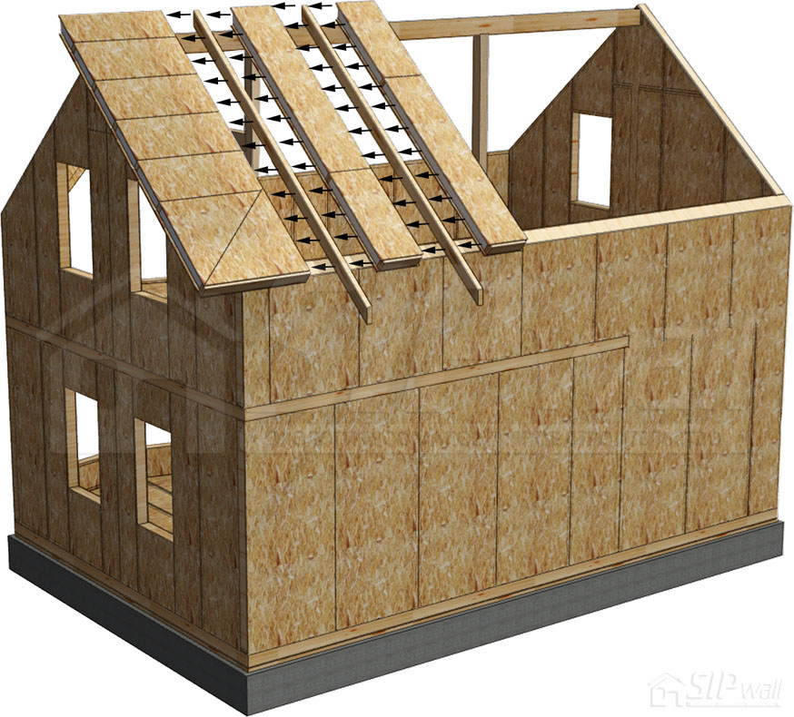
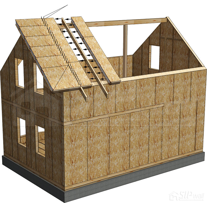
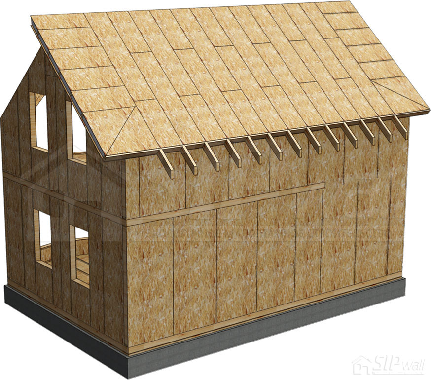
The rafter is the load-bearing element of the roof covering, taking the loads from snow cover, wind and the weight of the covering. It is made of dry planed timber or board (37 × 197 mm, 74 × 147 mm), depending on the thickness of the roof panels. It is built up in the same way as the joists built into the floor panels. Installation of the roof panels starts at one of the gables. The first panel is installed, then panels are added along the length of the gable. Next, a rafter is set in the pre-foamed groove, the panels are fixed to the rafter with screws, and then the process repeats (adding panels and rafters along the ridge beam). The rafters are fixed to the load-bearing elements with JD plus screws or equivalents, one at each bearing (screw length depends on the thickness of the roof panels). All grooves are foamed with assembly foam before the rafters are installed.
- Fixing with screws to load-bearing walls:
- Floor panel 174 mm thick — JD plus screws 240 mm or equivalents
- Floor panel 224 mm thick — JD plus screws 300 mm or equivalents
- Fixing with screws to beams and purlins:
- Floor panel 174 mm thick — JD plus screws 260 mm or equivalents
- Floor panel 224 mm thick — JD plus screws 320 mm or equivalents
For the main structural details, see Appendix No. 2. Technical Solutions Album – SIP panel details: House roof.
Installing and fixing the strapping board
When a slope has been assembled, strapping is installed around the contour with the groove foamed. It is fixed with screws 3,5 × 41 mm through the OSB at a spacing of 150 mm.
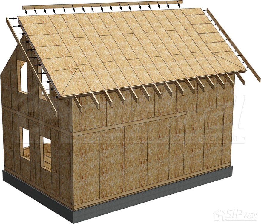
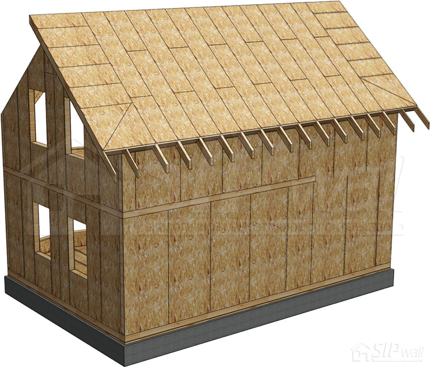
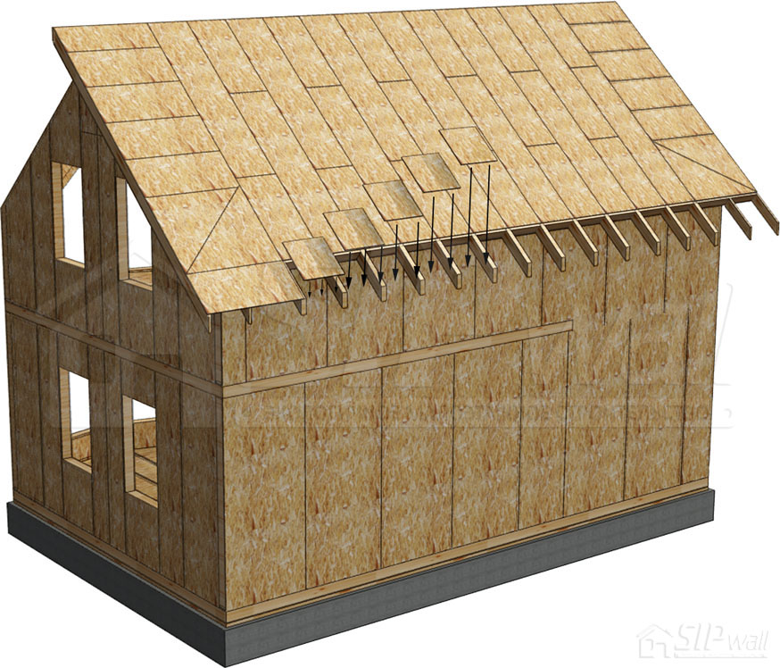
Sheathing the overhangs with OSB sheets
The next stage of roof assembly is sheathing the overhangs with OSB sheets. Fixing is to the rafter with screws 3,5 × 41 mm at a spacing of 100-150 mm.
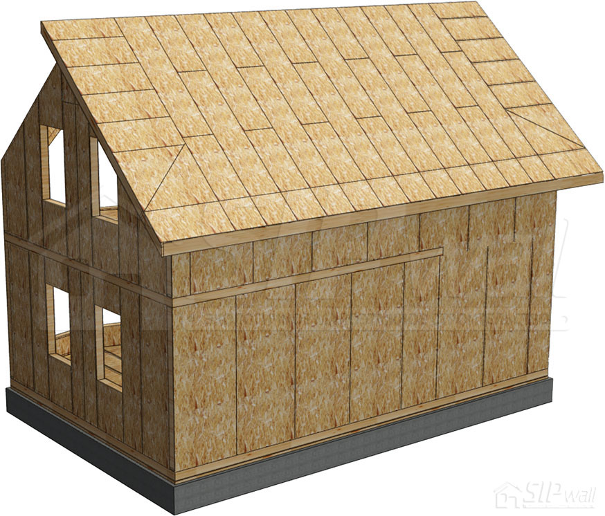
Installing the eaves board
When the roof is assembled, the eaves board is installed. The eaves board is fixed to every rafter, with 2 screws per eaves board. The remaining slopes are installed in the same way. For the main structural details, see Appendix No. 2. Technical Solutions Album – SIP panel details: House roof.
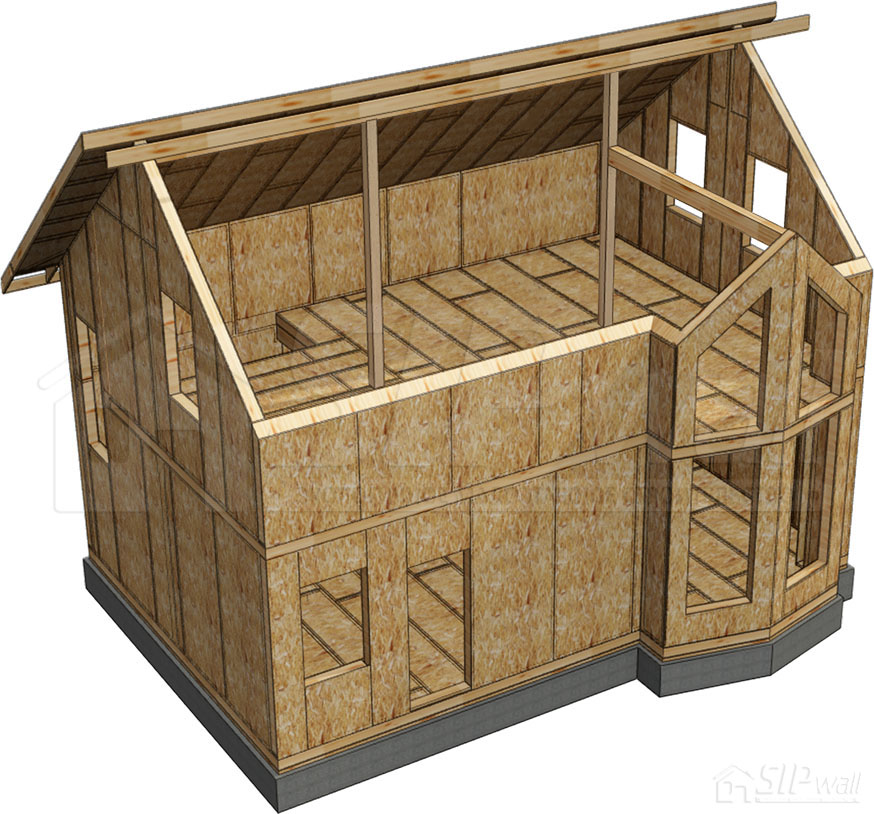
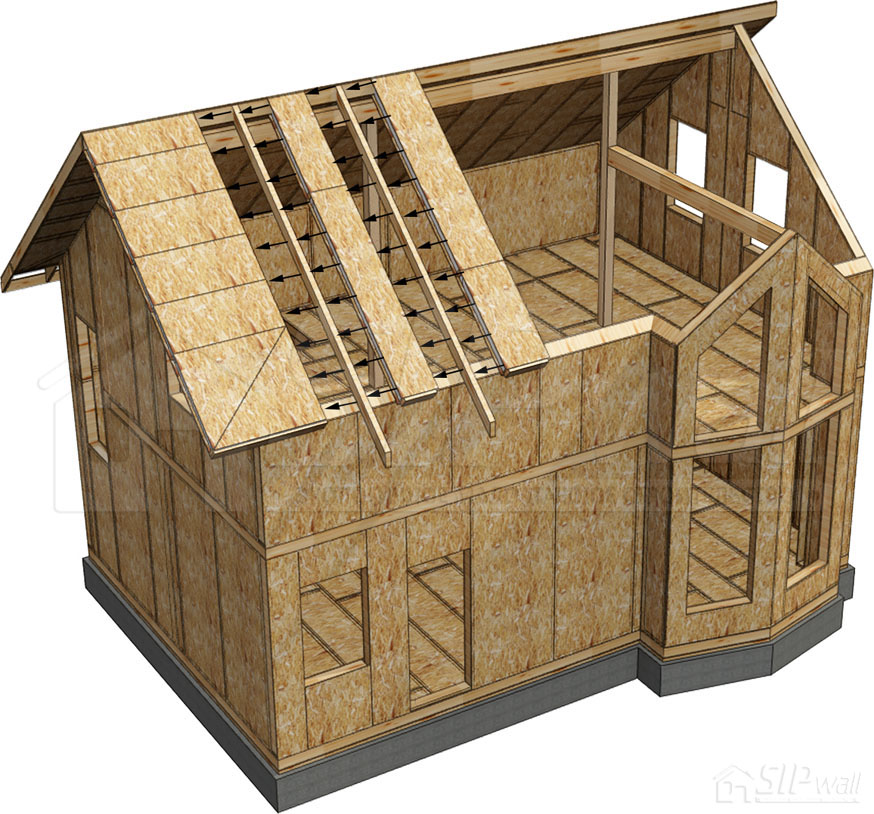
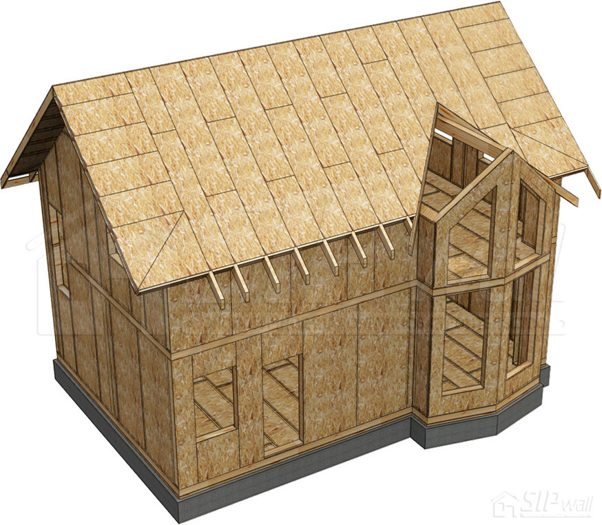
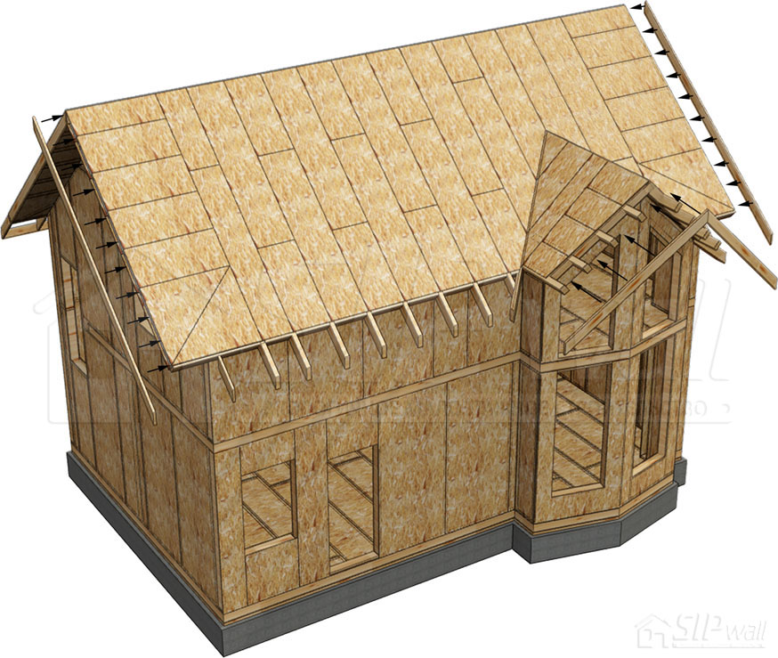
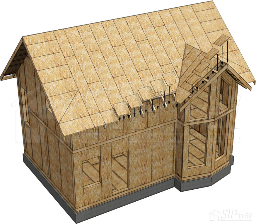
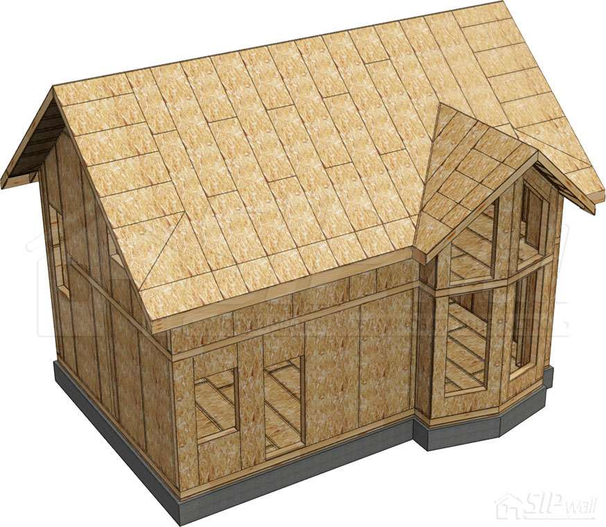
Before proceeding to the next stage of construction, the installation of the structure must be inspected in accordance with technical supervision (Appendix No. 1. Technical Supervision of the Construction of a SIP Panel House Using SIPwall Technology).
Installing a cold rafter system (gable)
Installing the sub-rafter structure of a cold roof
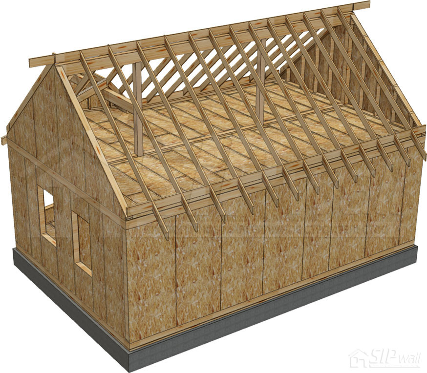
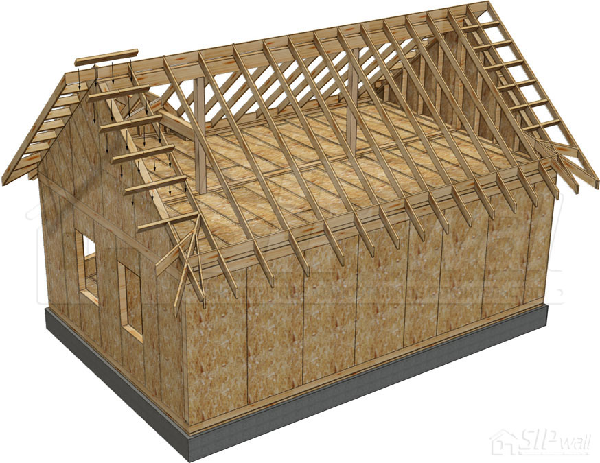
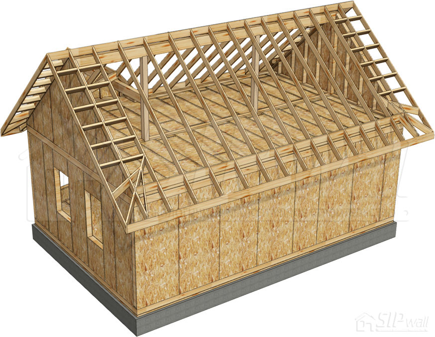
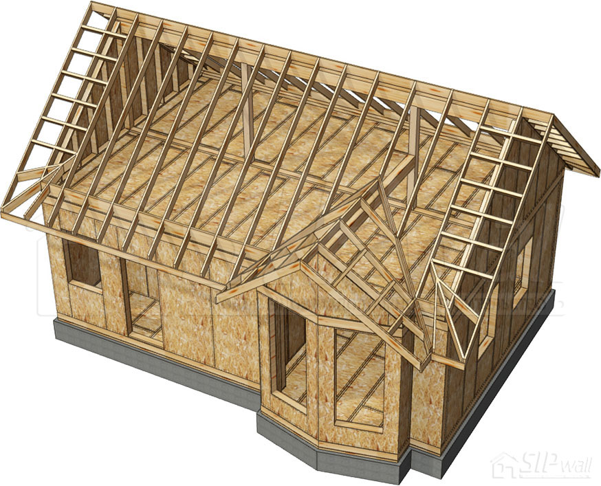
Assembly of the sub-rafter structure begins with studying the layout of all the elements. The mauerlat (wall plate) is built up from two boards 40 × 150 mm and fixed, as per the design, to the built-in floor joists with screws 6 × 160 mm, 2 pcs. at a spacing of 1250 mm, or at every second joist. If the floor has I-joists, the mauerlat is fixed at a spacing of 1250 mm, but not through an I-joist, with JD plus screws 8 × 300 mm or equivalents through the first board of the mauerlat. The strapping board 40 × 150 mm, for the attic posts, is fixed to the built-in floor joists with screws 4,2 × 90 m, 2 pcs. at a spacing of 1250 mm, or at every second joist. If the floor has I-joists, the strapping is fixed at a spacing of 1250 mm, but not through an I-joist, with JD plus screws 8 × 300 mm or equivalents. Installation of posts and beams begins with studying their layout and marking. Posts are fixed to the strapping board of the attic floor with reinforced angle brackets KPW-4 (105 × 105 × 90 × 2,5 mm). Beams and posts are fixed to each other with reinforced angle brackets KPW-4 (105 × 105 × 90 × 2,5 mm) and screws 6 × 80 mm. At a support, beams are joined along their length with a metal plate 100 × 300 mm and screws 3,5 × 41 mm. A beam may be fixed to another beam with an OBR-R timber support 150 × 150 × 76 × 2 mm and screws 6 × 80 mm. For the main structural details, see Appendix No. 5. Technical Solutions Album – Rafter system.
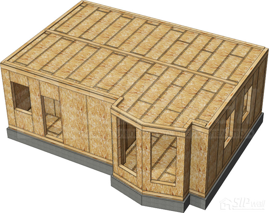
Gables are assembled in the same way as load-bearing frame walls and sheathed on the outside with OSB 12 mm as per the design.
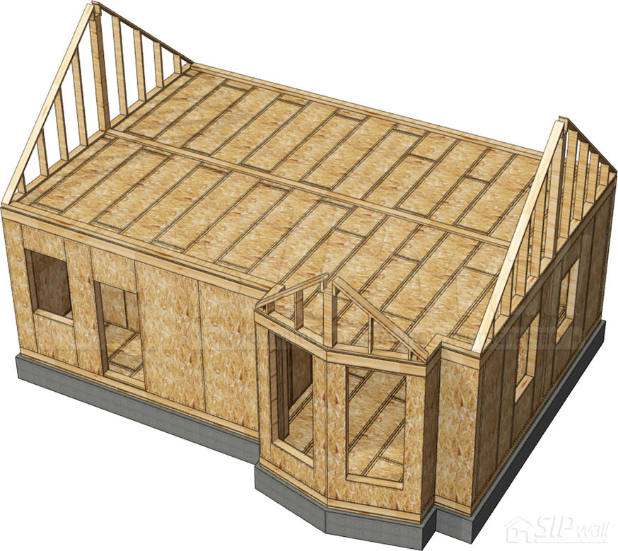
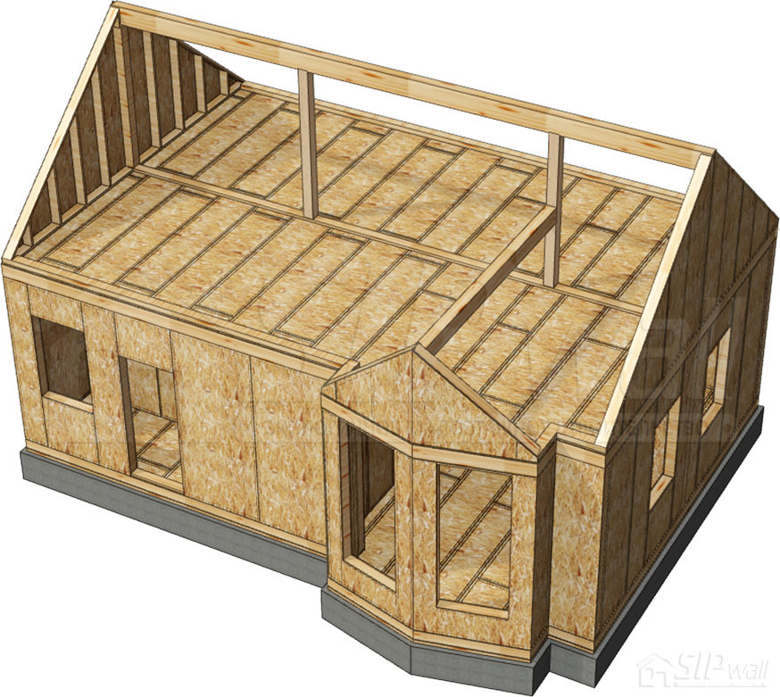
Installing a cold rafter system (gable roof)
Rafters are fixed to the mauerlat with reinforced angle brackets KPW-4 (105 × 105 × 90 × 2,5 mm) and screws 3,5 × 41 mm. Blocking between the rafters is fixed with screws 4,2 × 90 mm, 4 pcs. per block. Double rafters are fixed together with screws 4,2 × 64 mm in a staggered pattern at a spacing of 150 mm. The eaves board is fixed to each rafter it crosses with two screws 4,2 × 64 mm. At a support, single rafters are fixed with screws 6 × 120 mm, 3 pcs. per detail, and double rafters are fixed with screws 6 × 160 mm, 3 pcs. For the main structural details, see Appendix No. 5. Technical Solutions Album – Rafter system.
For the main structural details, see Appendix No. 5. Album of Technical Solutions – Rafter System Installation. Before proceeding to the next stage of construction, the installation of the structure must be inspected in accordance with technical supervision (Appendix No. 1. Technical Supervision of the Construction of a SIP Panel House Using SIPwall Technology).
Installation of a cold rafter system (hip roof)
For the main structural details, see Appendix No. 5. Album of Technical Solutions – Rafter System Installation.
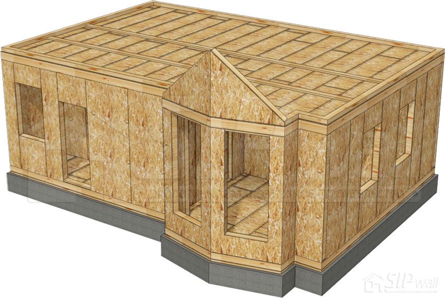
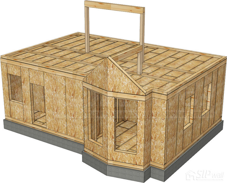
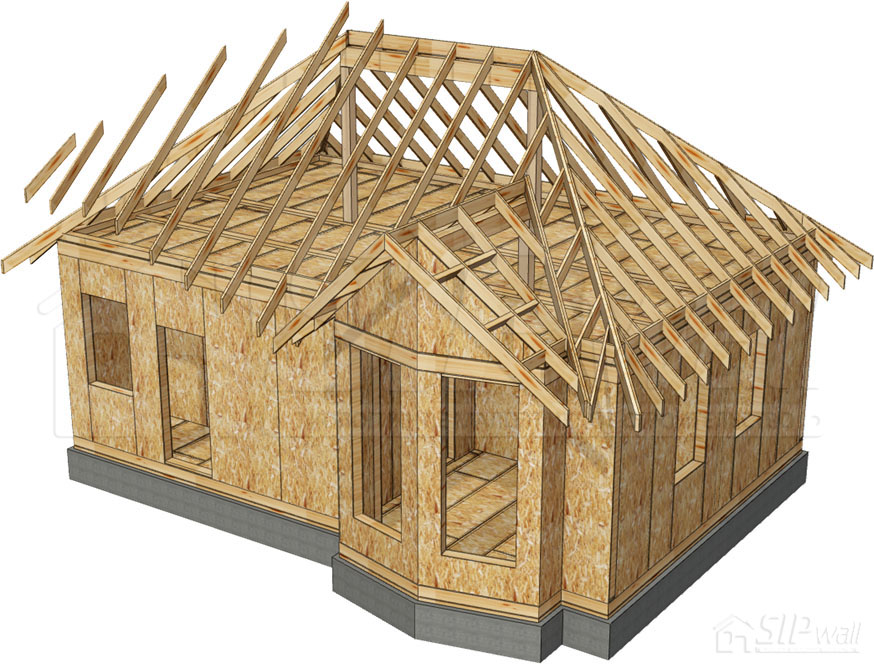
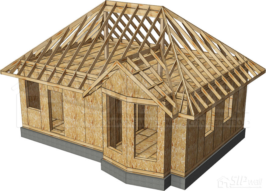
Before proceeding to the next stage of construction, the installation of the structure must be inspected in accordance with technical supervision (Appendix No. 1. Technical Supervision of the Construction of a SIP Panel House Using SIPwall Technology).
Book contents