1. Table of maximum spans for SIP floors
| Maximum span, mm | Joist spacing, mm | Joist section, mm | Load, kg/m² | Floor thickness, mm |
|---|---|---|---|---|
| 2100 | 620 | 74 × 97 | 250 | 124 |
| 1700 | 1250 | 74 × 97 | 250 | 124 |
| 3300 | 620 | 74 × 147 | 250 | 174 |
| 2650 | 1250 | 74 × 147 | 250 | 174 |
| 4500 | 620 | 74 × 197 | 250 | 224 |
| 3500 | 1250 | 74 × 197 | 250 | 224 |
When using the floors of the House, follow these requirements: without a specially developed design agreed with our company: do not make openings in the floors; do not route services through the floors; do not break the vapor barrier and waterproofing membranes in floors above a technical crawl space, a cold basement or under a cold attic; do not allow the floor insulation to get wet or over-moistened; do not damage the waterproofing on balconies, terraces and in bathrooms, including where the waterproofing meets door frames, walls and partitions.
Failure to comply with the listed requirements may lead to reduced load-bearing capacity of the floors, loss of sound insulation properties and rainwater leaks.
2. SIP floor on a timber grillage
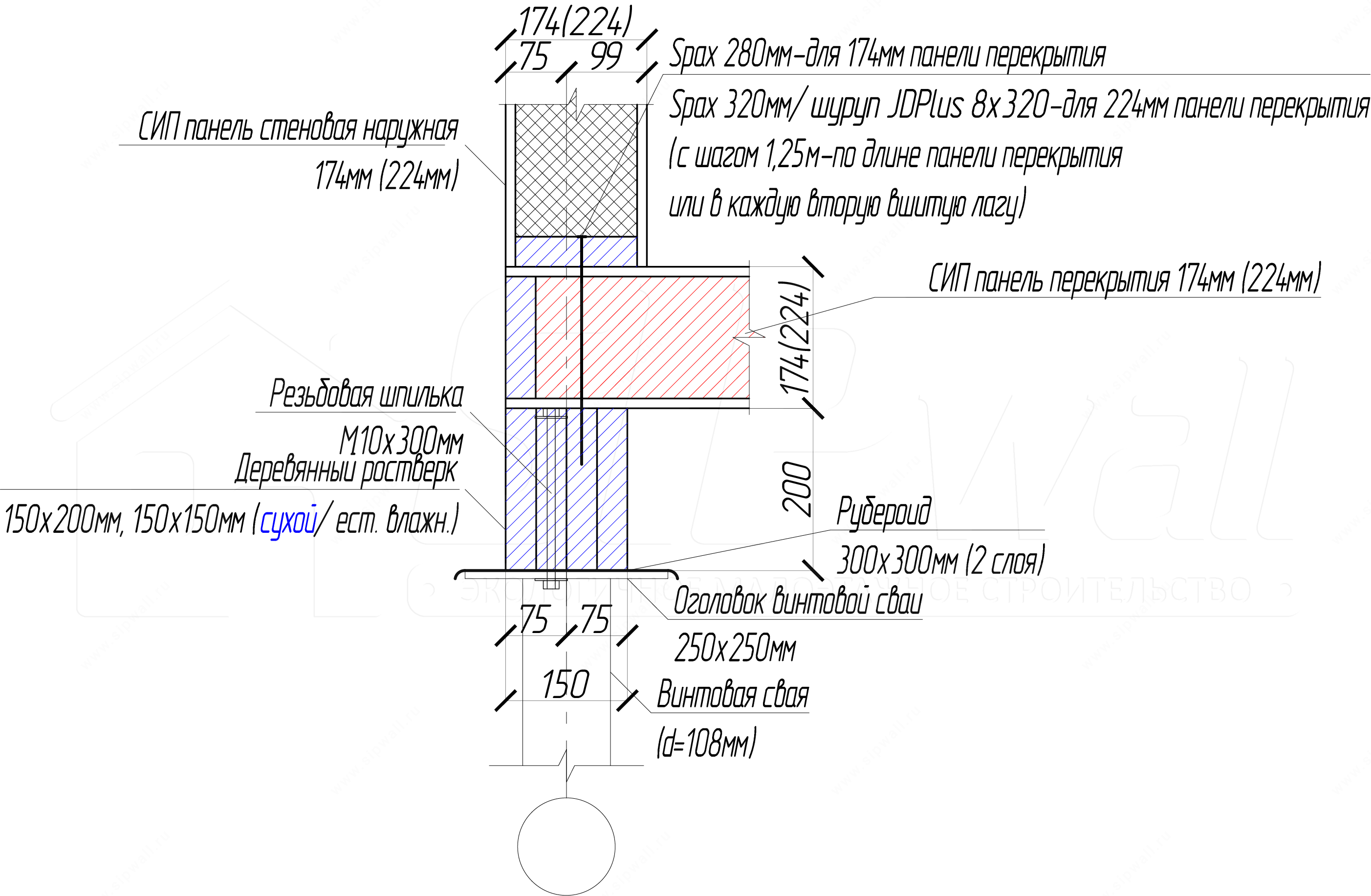
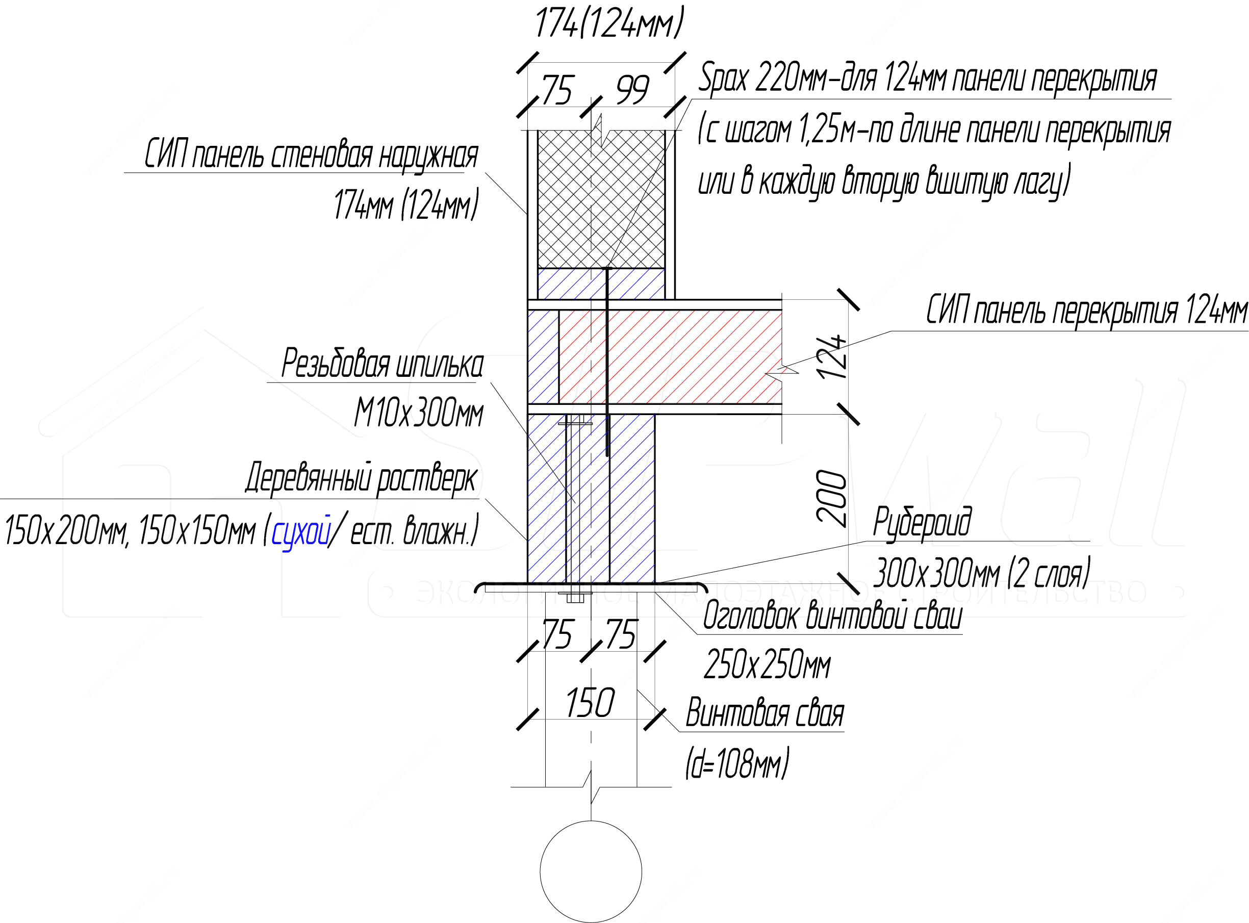
joists for 224 mm panels are built up from two boards 37 × 197 mm with screws 4,2 × 64 mm in a staggered pattern at a spacing of 250 mm.
3. SIP floor on a reinforced concrete foundation
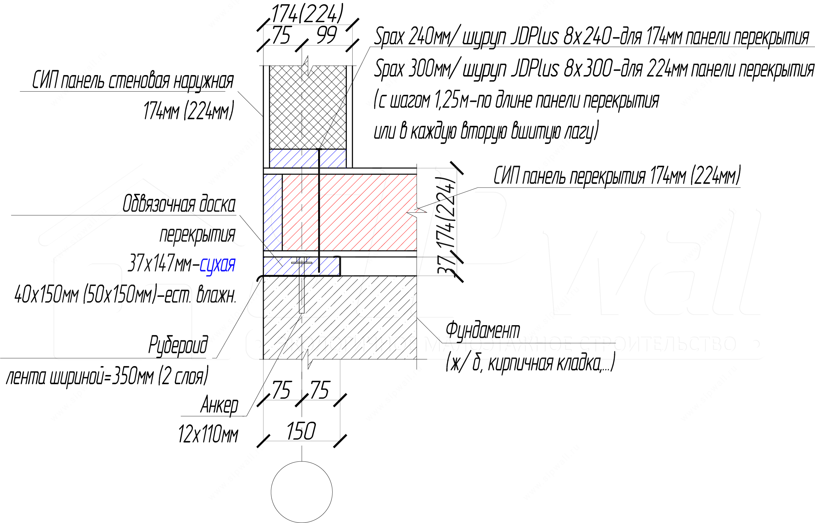
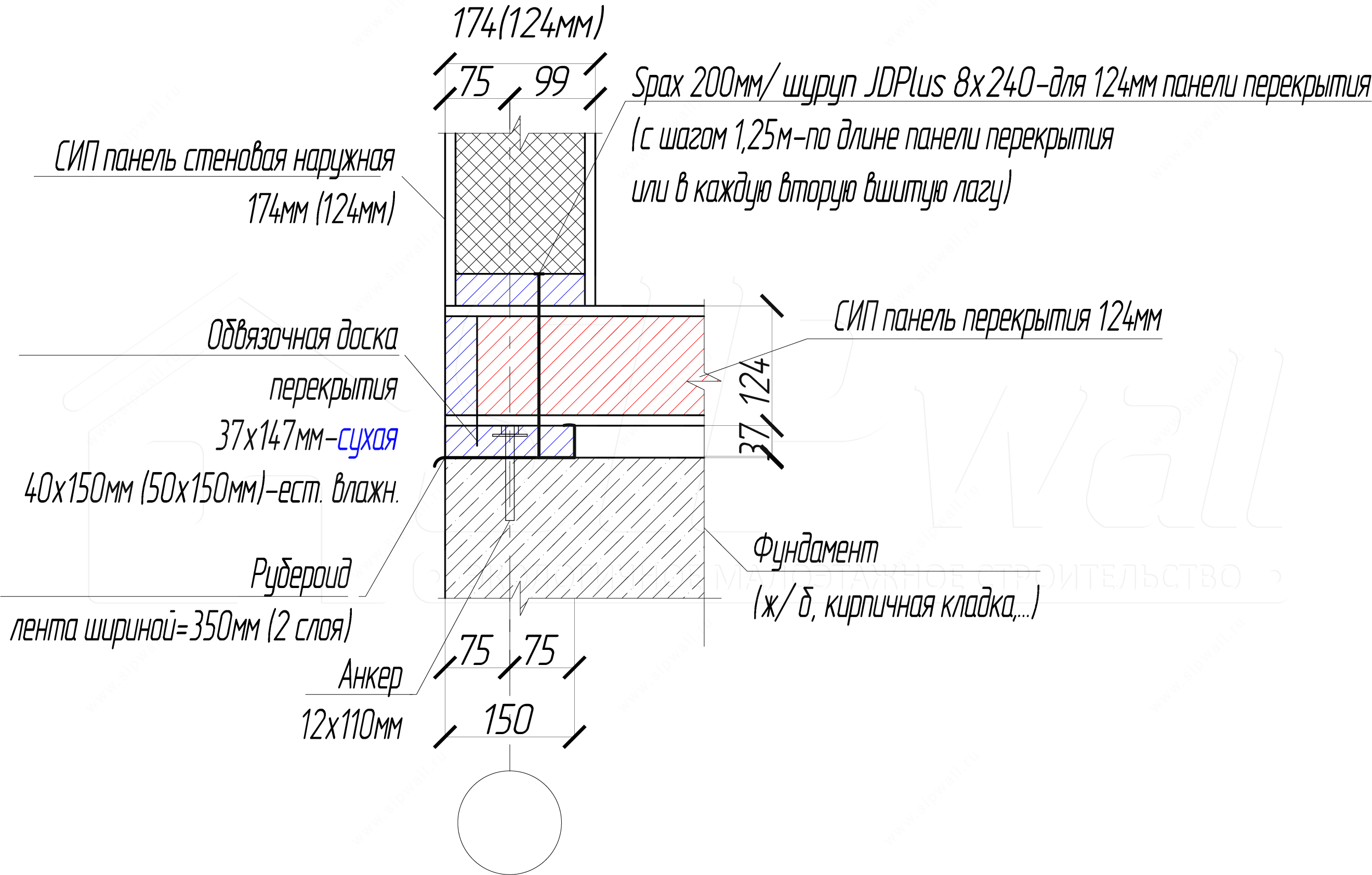
joists for 224 mm panels are built up from two boards 37 × 97 mm with screws 4,2 × 64 mm in a staggered pattern at a spacing of 250 mm.
4. SIP panel floor on a timber grillage with channel strapping of the piles

5. SIP floor on a support board with channel strapping of the piles
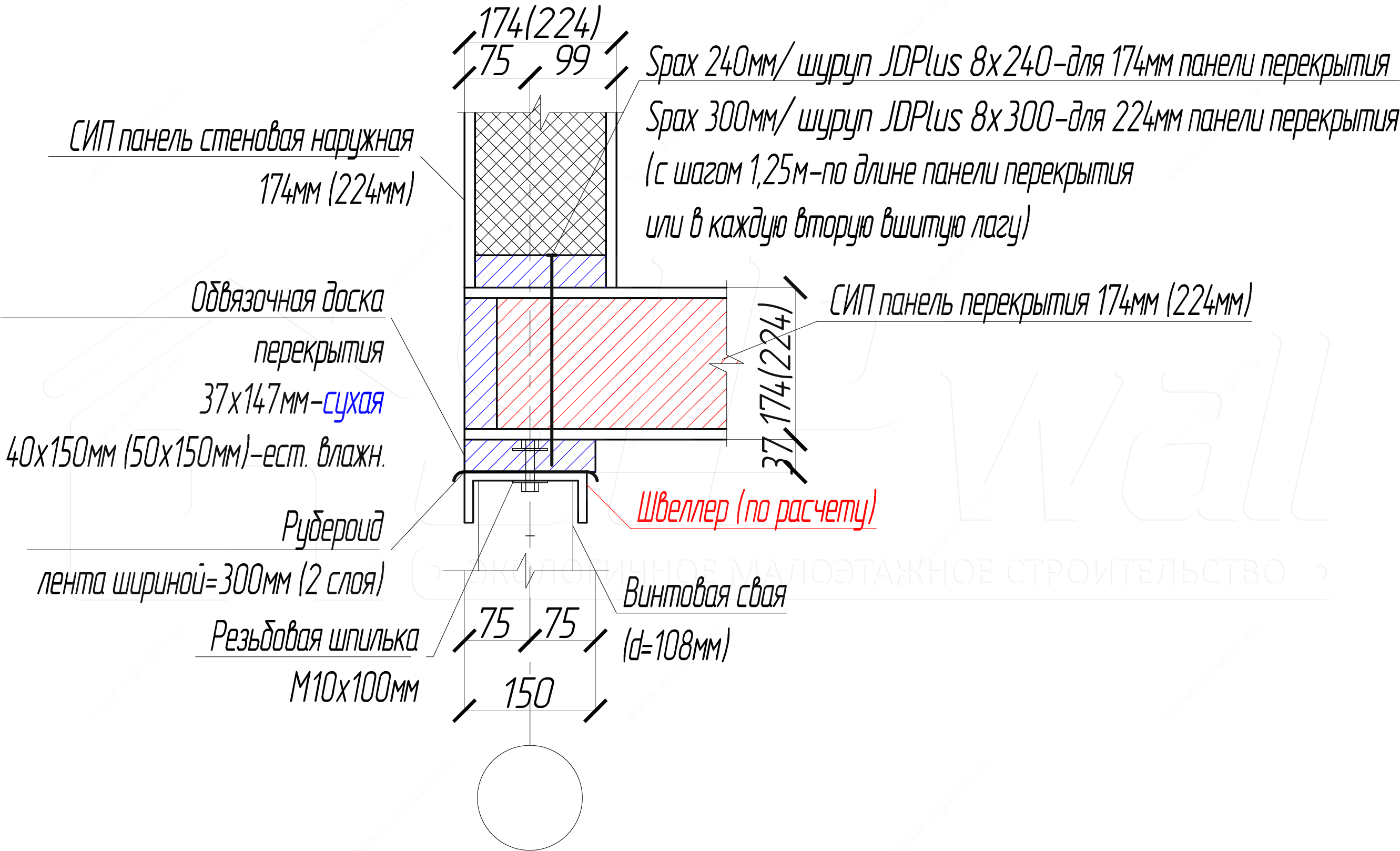
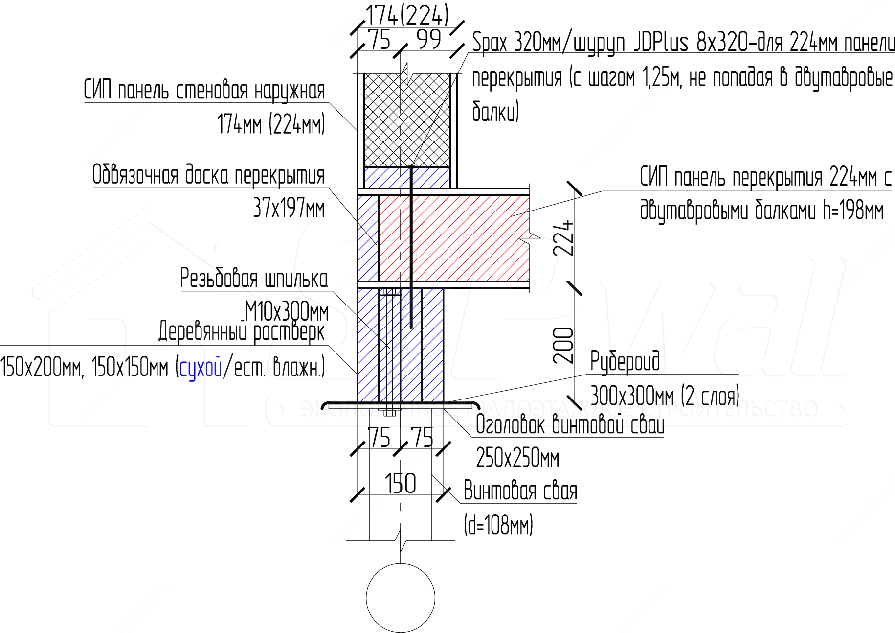
joists for 224 mm panels are built up from two boards 37 × 197 mm with screws 4,2 × 64 mm in a staggered pattern at a spacing of 250 mm.
6. SIP floor with I-joists on a timber grillage
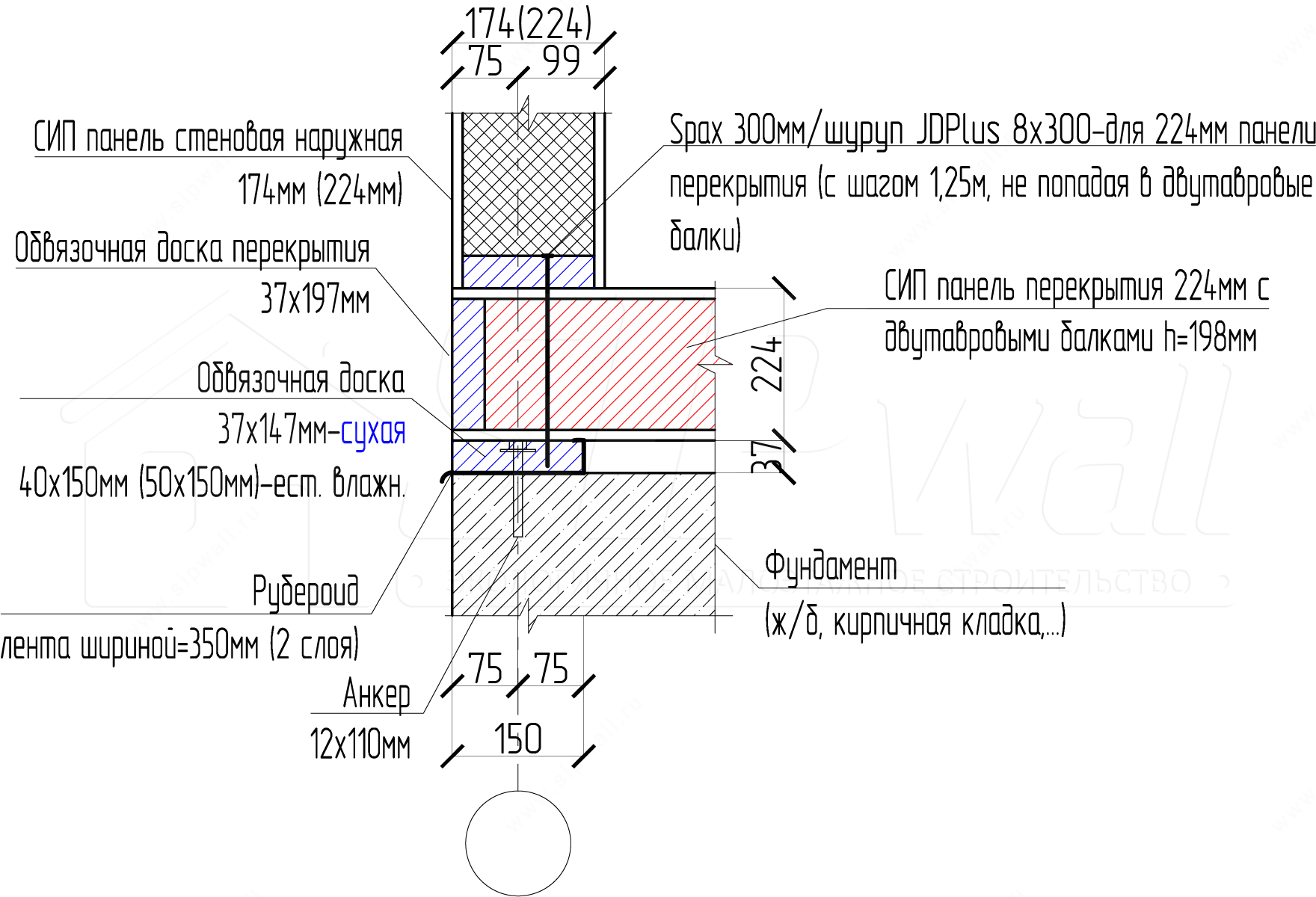
7. SIP floor with I-joists on a reinforced concrete foundation
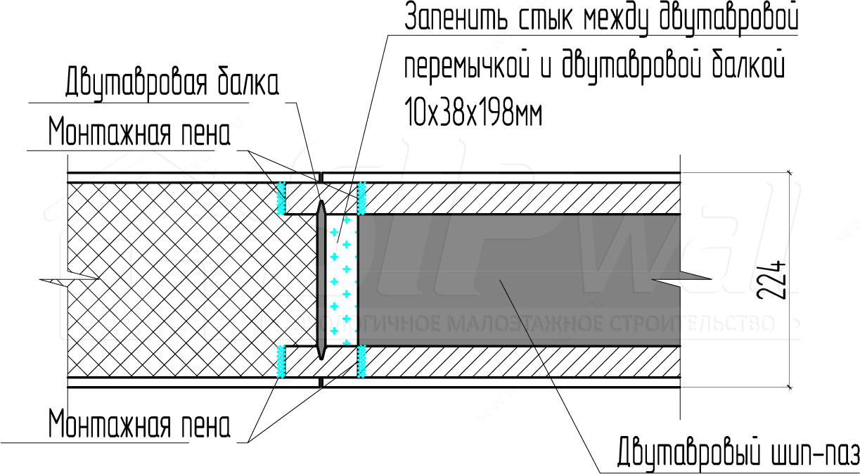
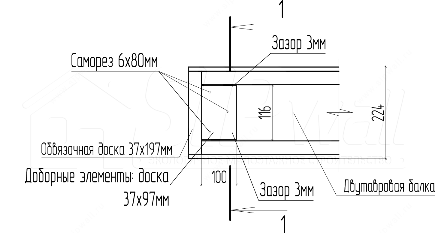
the maximum span for SIP floors with I-joists is 4000 mm.
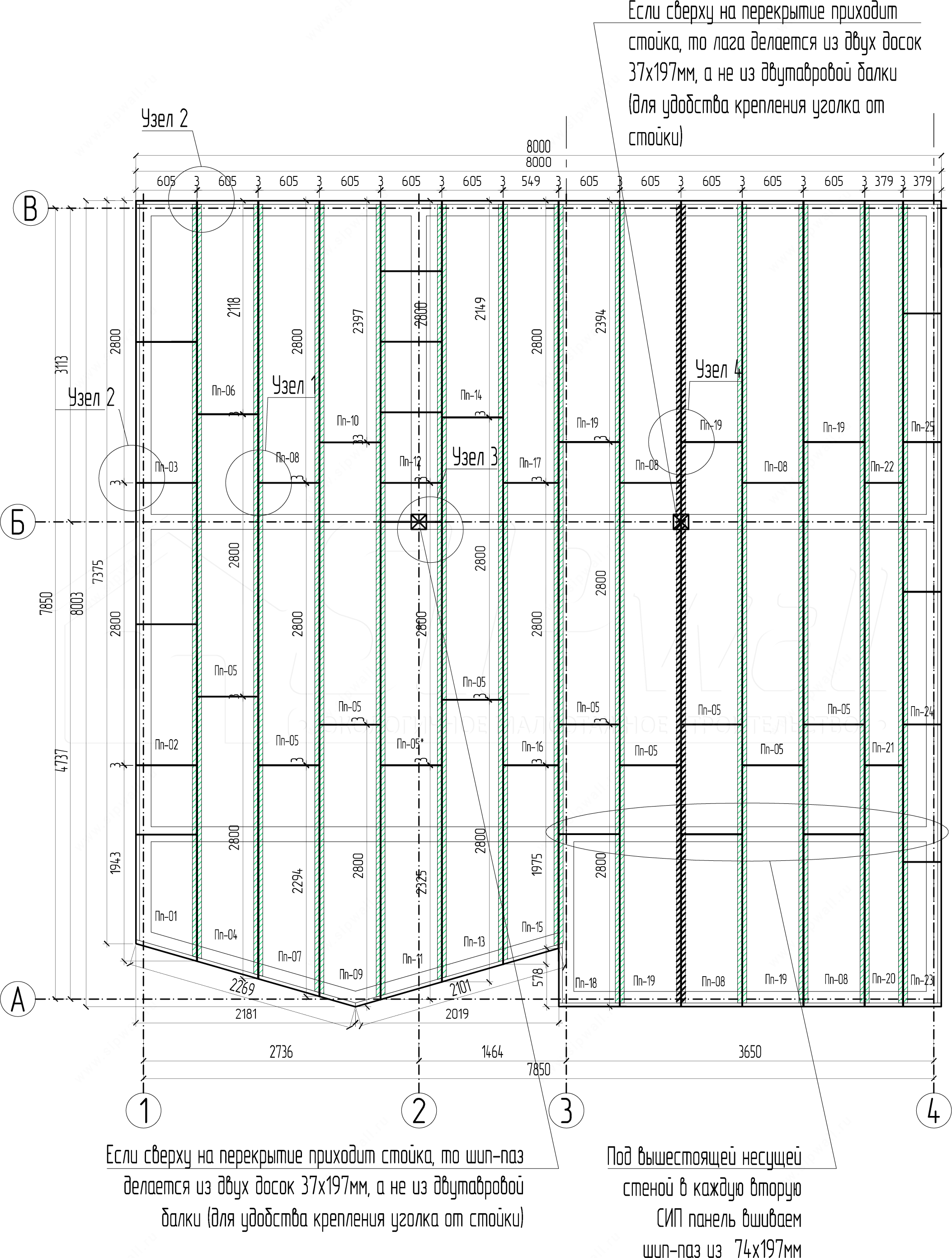
SIP floor with I-joists
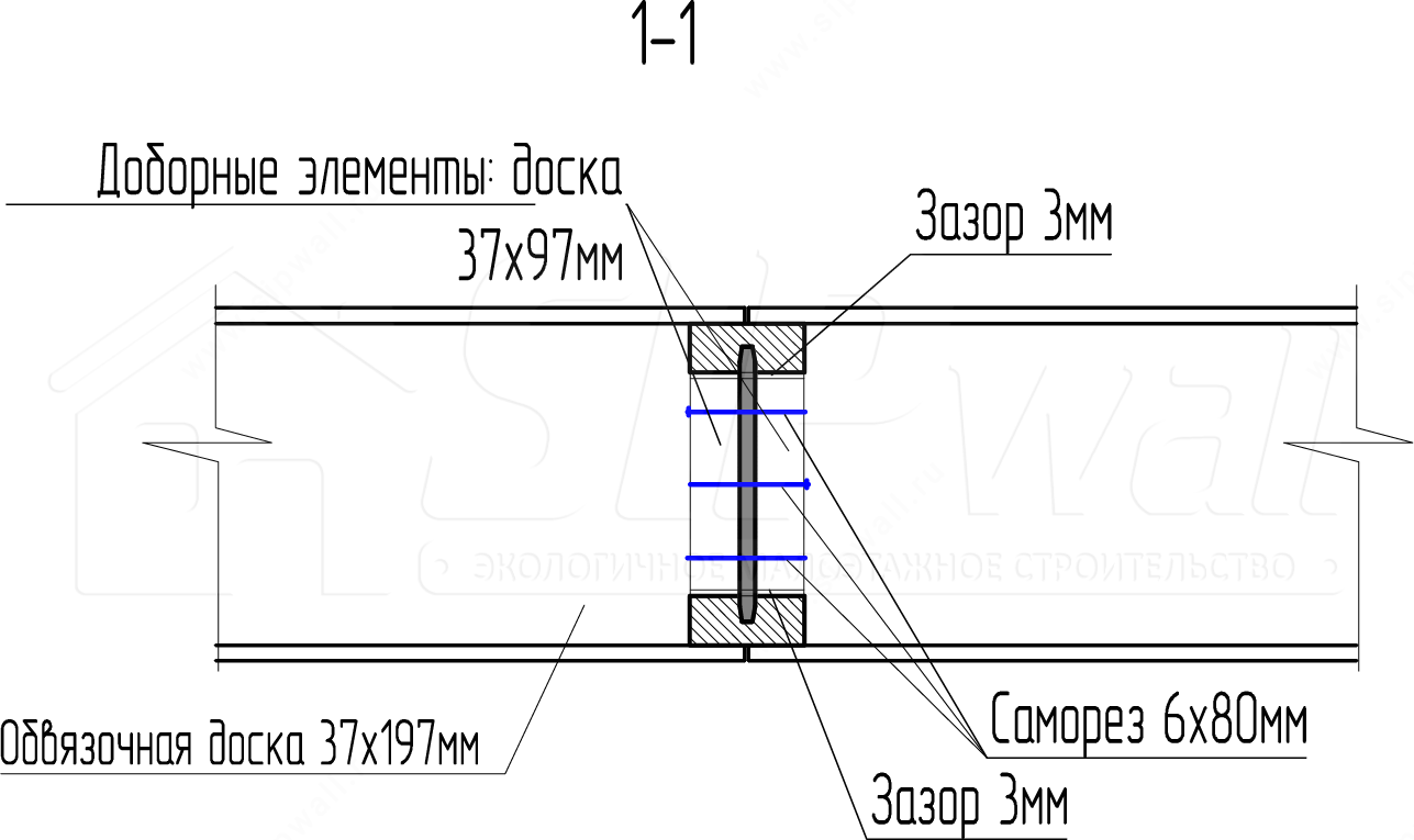
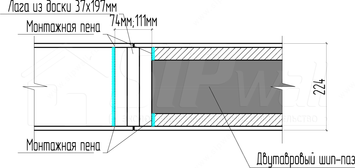
- Detail 1
- Detail 2 (apply around the whole perimeter of the external walls at every second joist)
- Note: apply at every second joist on axes А and В, and in every tongue-and-groove joint on axes 1 and 4. Make the recess for the reinforcement on site.
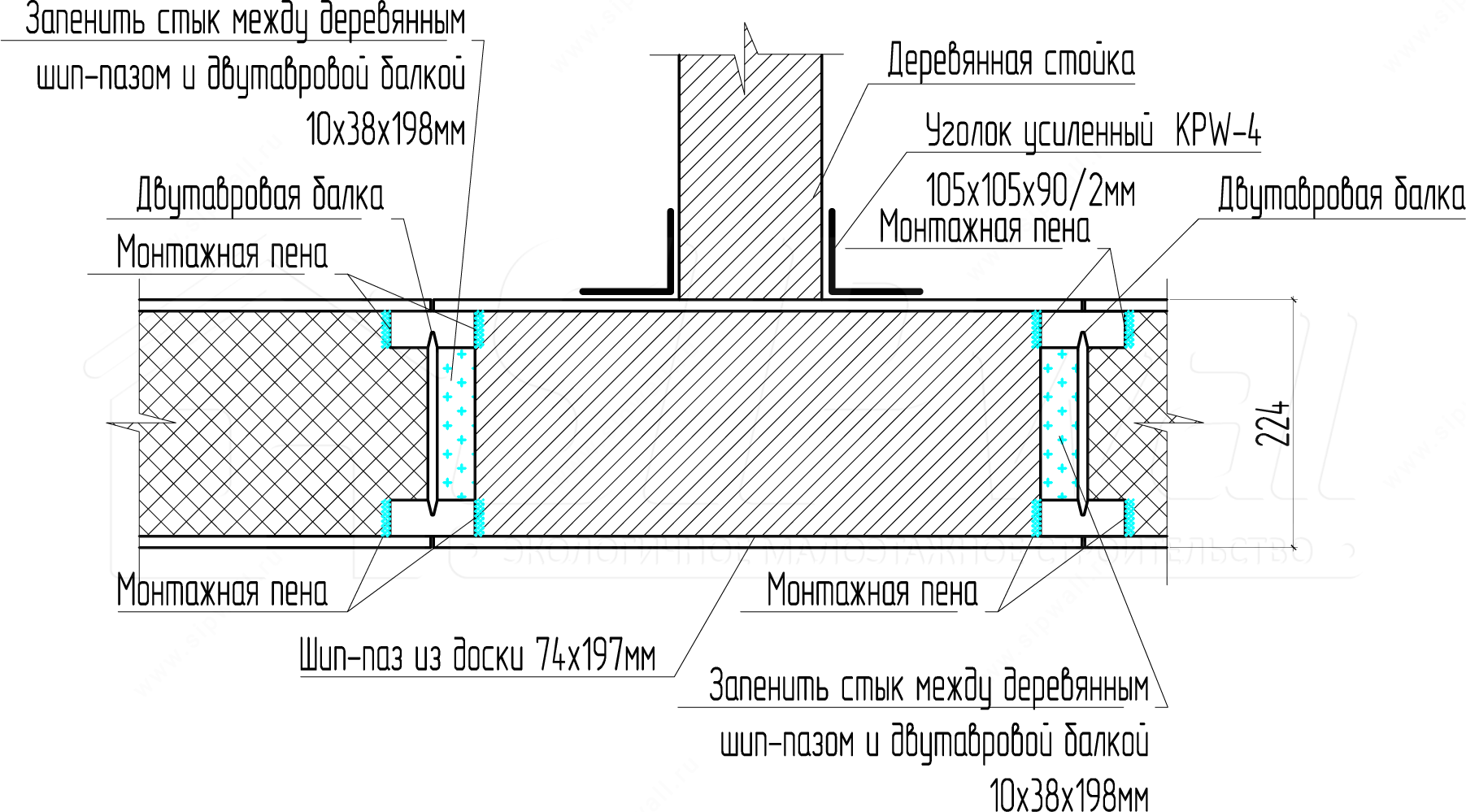
- Detail 3
- Detail 4