- Plan of the intermediate/attic I-joist floor
- Details
- Specification of frame elements and dry lumber for the floor at level +3,063
1. Plan of the intermediate/attic I-joist floor
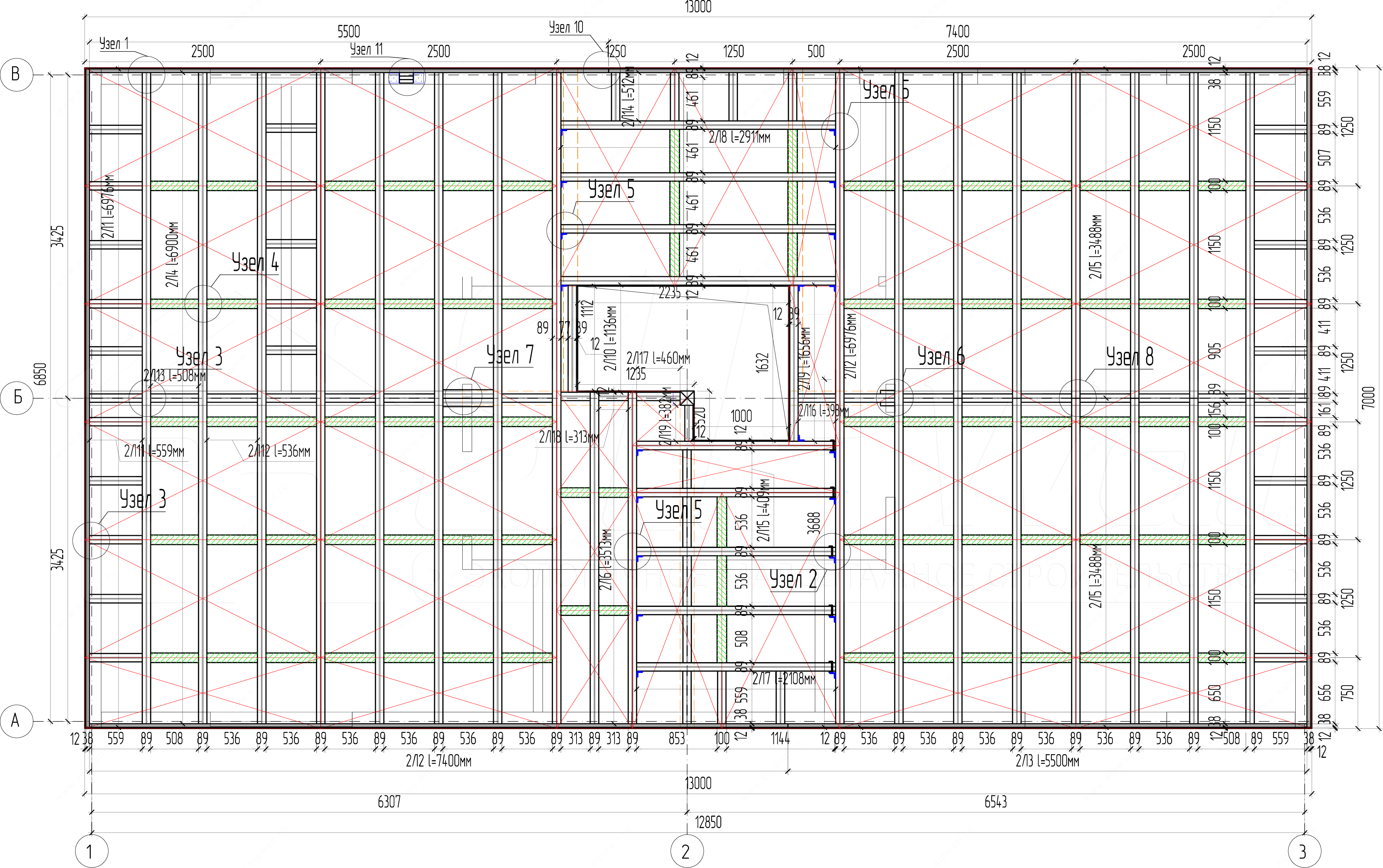
Notes:
1. Carry out the floor reinforcement of I-joists according to the details shown on the drawing.
2. If the floor is made of I-joists, a balcony uses boards, not I-joists.
2. Details
Detail 1
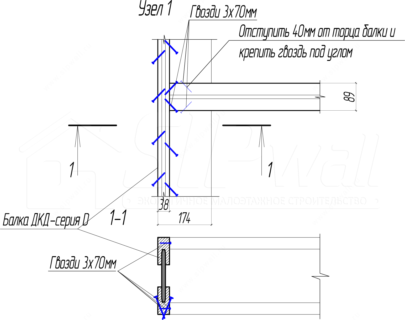
Notes:
1. Fix the I-joist blocking to the I-joists and the top strapping board of the first-floor wall panels with nails 3 × 70 mm, 4 pcs. per bottom flange (2 pcs. into the joist and 2 pcs. into the strapping timber) and 2 pcs. into the top flange.
2. Fix the I-joist strapping beam to the support with nails 3 × 70 mm at a spacing of 150 mm, offset relative to the opposite side.
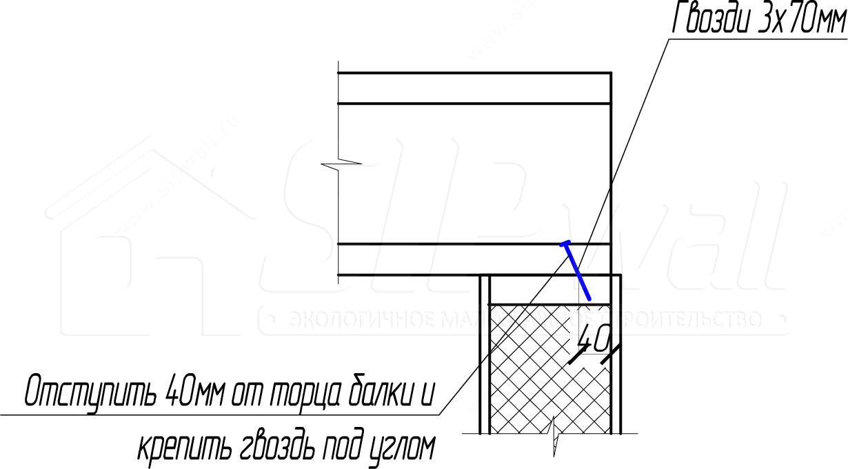
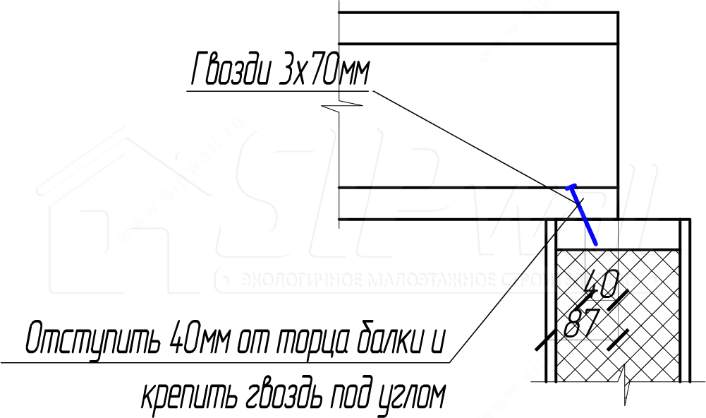
Notes:
1. Fix the I-joists to the top strapping board of the first-floor wall panels with nails 3 × 70 mm, 4 pcs. per bottom flange (per detail).
Detail 1*
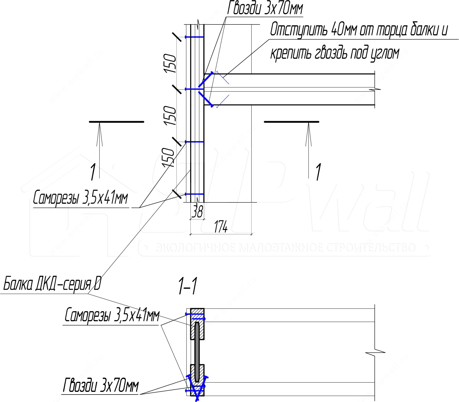
Notes:
1. Fix the I-joist blocking to the I-joists and the top strapping board of the first-floor wall panels with nails 3 × 70 mm, 4 pcs. per bottom flange (2 pcs. into the joist and 2 pcs. into the strapping timber) and 2 pcs. into the top flange.
2. Fix the OSB around the floor perimeter with screws 3,5 × 41 mm at a spacing of 150 mm to the top and bottom flanges of the floor I-joists.
Detail 2
Notes:
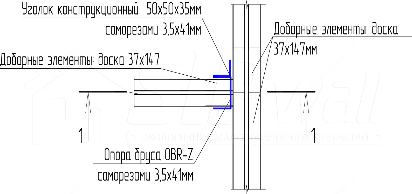
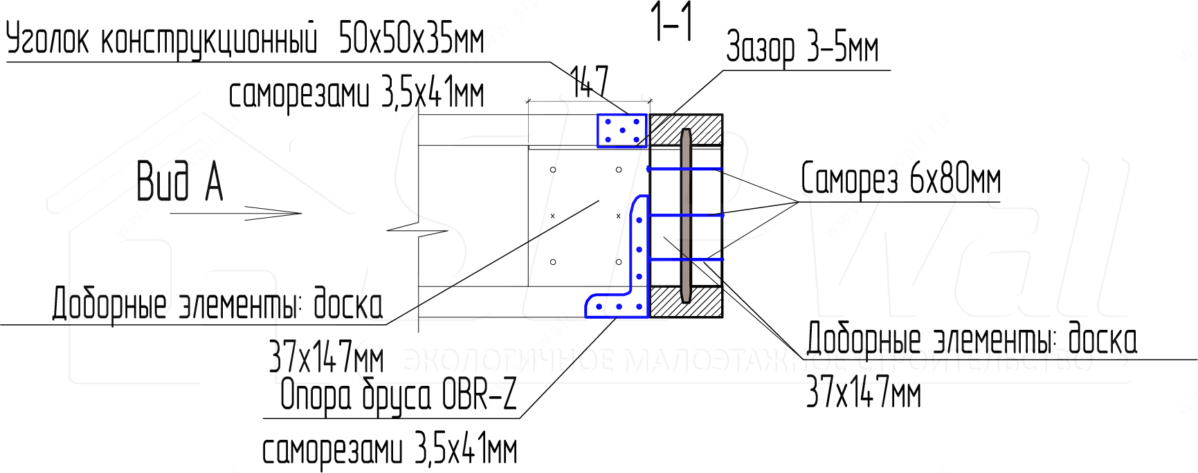
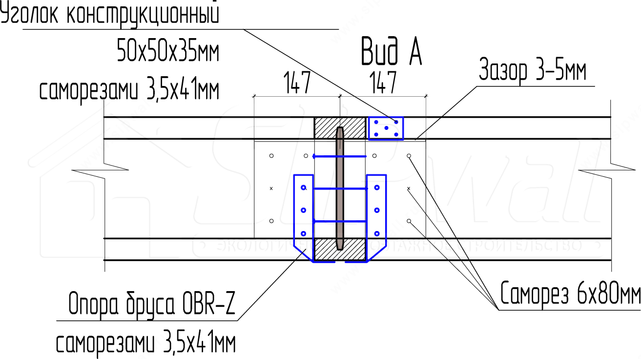
1. Fix I-joists to other I-joists on an OBR-Z timber support 25 × 140 × 76 mm (split, left + right = 1 pcs.) with screws 3,5 × 41 mm through board inserts 37 × 147 mm.
2. Fix the board inserts 37 × 147 mm to each other with screws 6 × 80 mm, 4-6 pcs. per board.
3. Besides the timber support, fix the joist at the top flange with a structural angle 50 × 50 × 35 mm and screws 3,5 × 41 mm, 6-8 pcs. per angle.
Detail 3
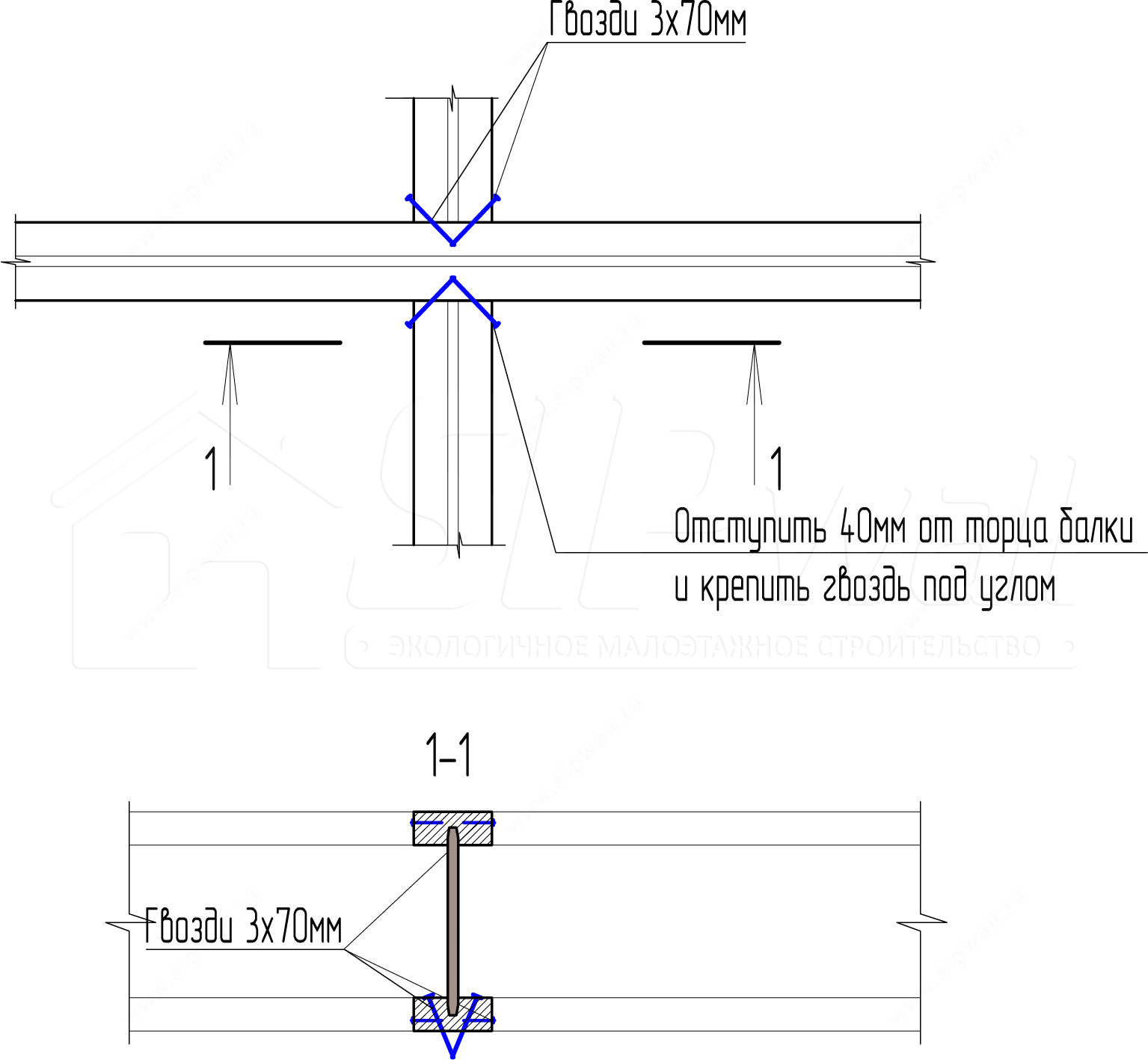
Note:
Fix the I-joist blocking to the I-joists and the top strapping board of the first-floor wall panels with nails 3 × 70 mm, 4 pcs. per bottom flange (2 pcs. into the joist and 2 pcs. into the strapping timber) and 2 pcs. into the top flange.
Detail 4
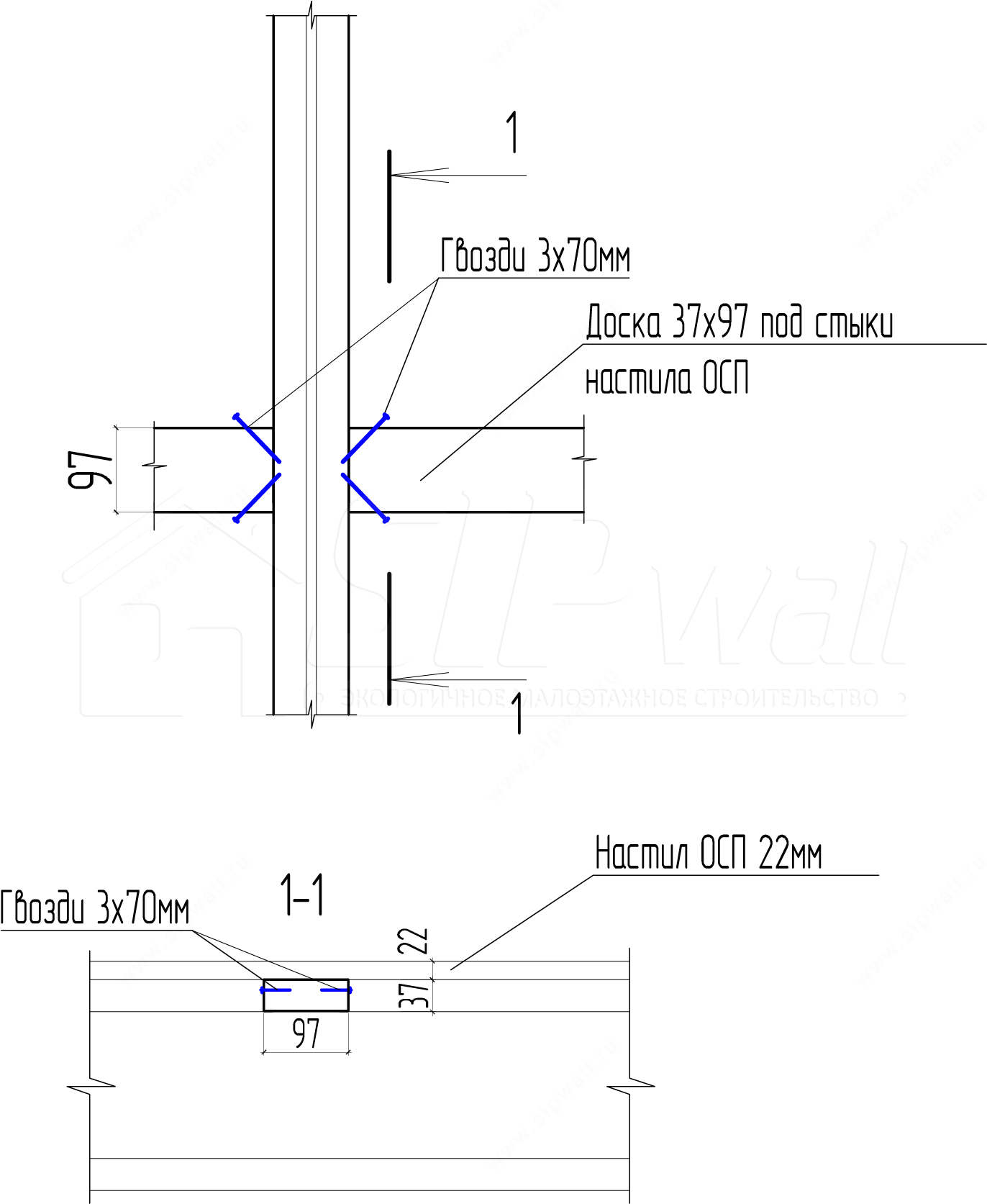
Note:
Under the joints of the 22 mm OSB decking, fix board blocking 37 × 97 mm to the top flange of the I-joist with nails 3 × 70 mm (4 pcs. per block).
Detail 5
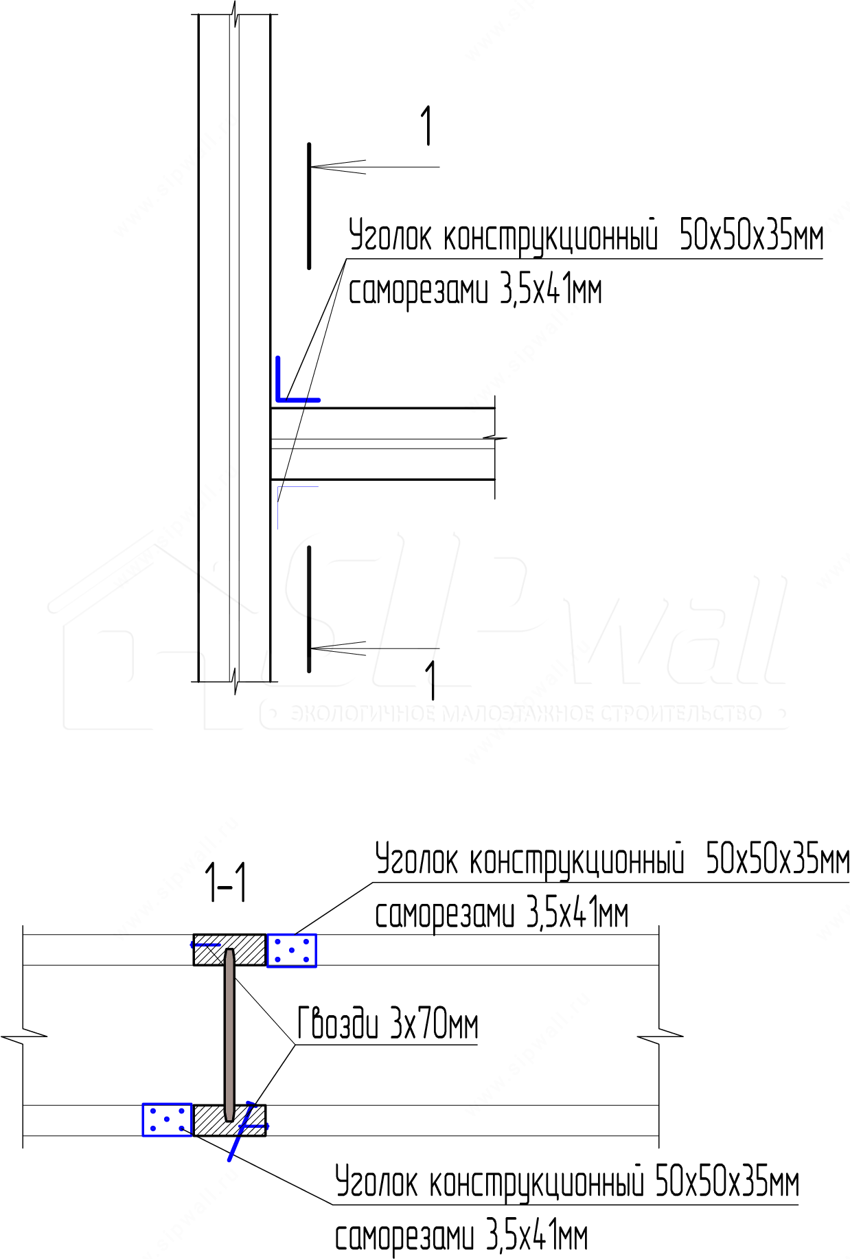
Note:
I-joists that meet other I-joists as a cantilever or on a support are fixed with structural angles 50 × 50 × 35 mm (1 angle on each flange), and on the other side of the angle with nails 3 × 70 mm, 2 pcs. per bottom flange (1 pcs. into the joist and 1 pcs. into the strapping timber) and 1 pcs. into the top flange.
Detail 6
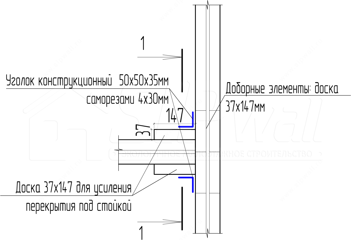
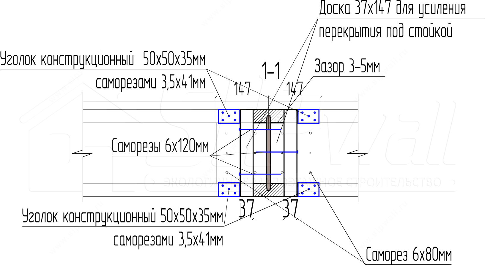
Notes:
1. Reinforce the I-joist detail under the post with an extra board 37 × 147 mm, fixing them together with screws 6 × 120 mm, 4-6 pcs. Fix the extra boards together at the adjacent joist with screws 6 × 80.
2. Fix the detail between the flanges of the I-joists with structural angles 50 × 50 × 35 mm and screws 3,5 × 41 mm (4 pcs.).
3 In addition, fix the bottom flange with nails 3 × 70 mm to the top strapping timber of the first-floor walls (2-4 pcs.).
Detail 6*
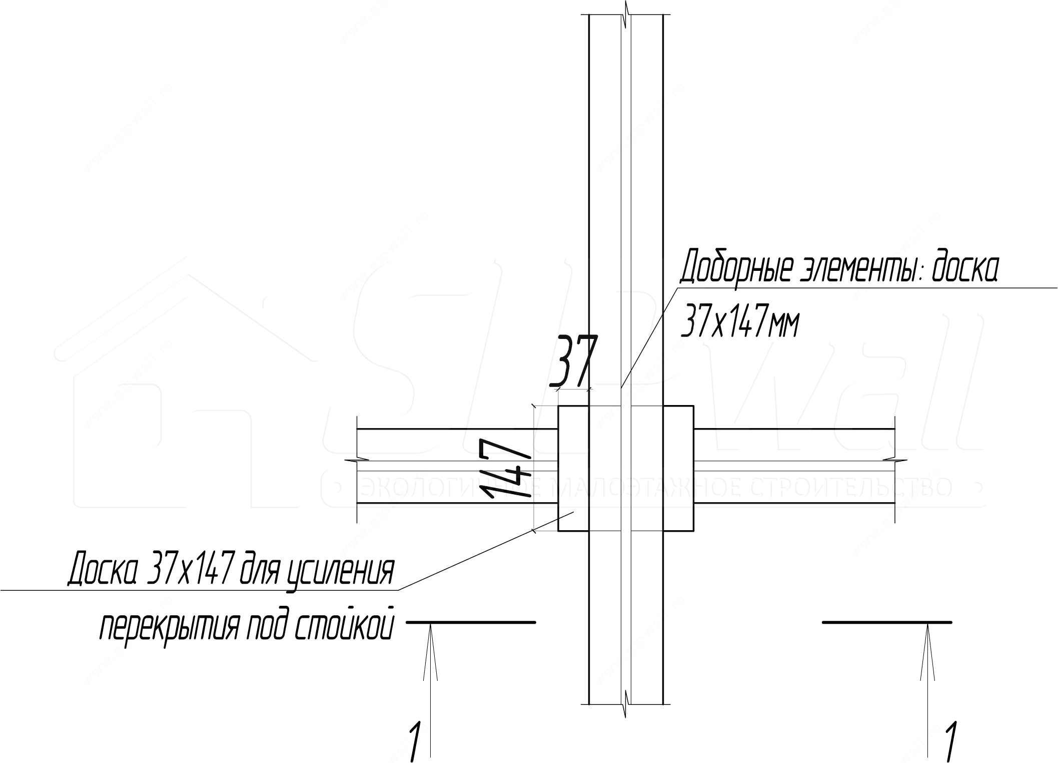
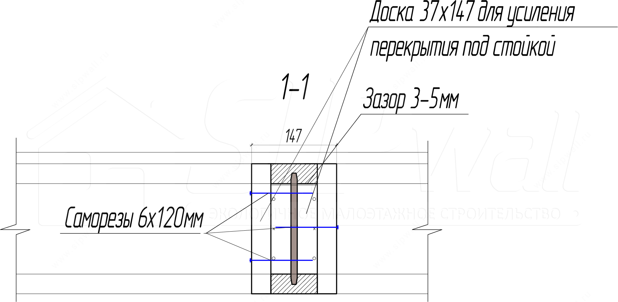
Notes:
1. Reinforce the I-joist detail under the post with an extra board 37 × 147 mm, fixing them together with screws 6 × 120 mm, 4-6 pcs. Fix the extra boards together at the adjacent joist with screws 6 × 80 mm.
2. In addition, fix the bottom flange with nails 3 × 70 mm to the top strapping timber of the first-floor walls (2-4 pcs.).
Detail 6**
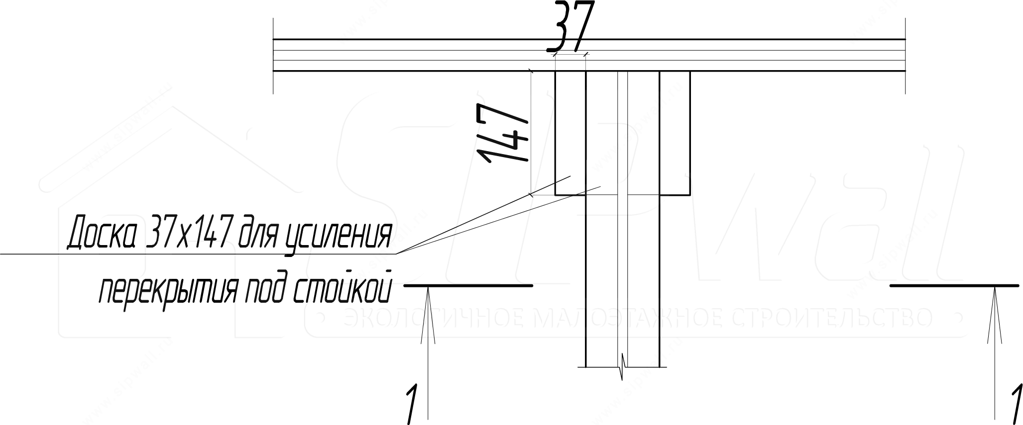
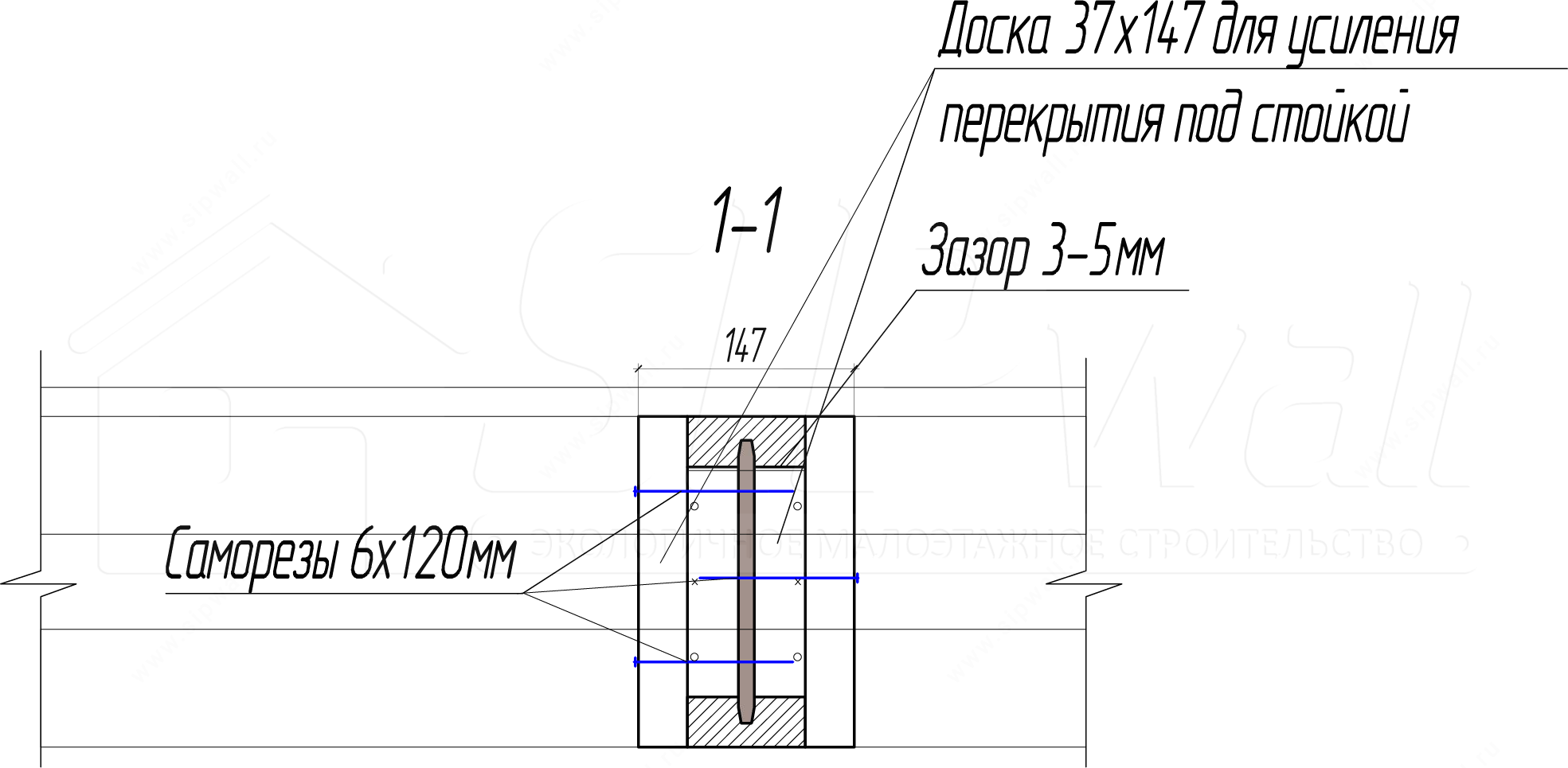
Notes:
1. Reinforce the I-joist detail under the post with an extra board 37 × 147 mm, fixing them together with screws 6 × 120 mm, 4-6 pcs. Fix the extra boards together at the adjacent joist with screws 6 × 80.
2. In addition, fix the bottom flange with nails 3 × 70 mm to the top strapping timber of the first-floor walls (2-4 pcs.).
Detail 7
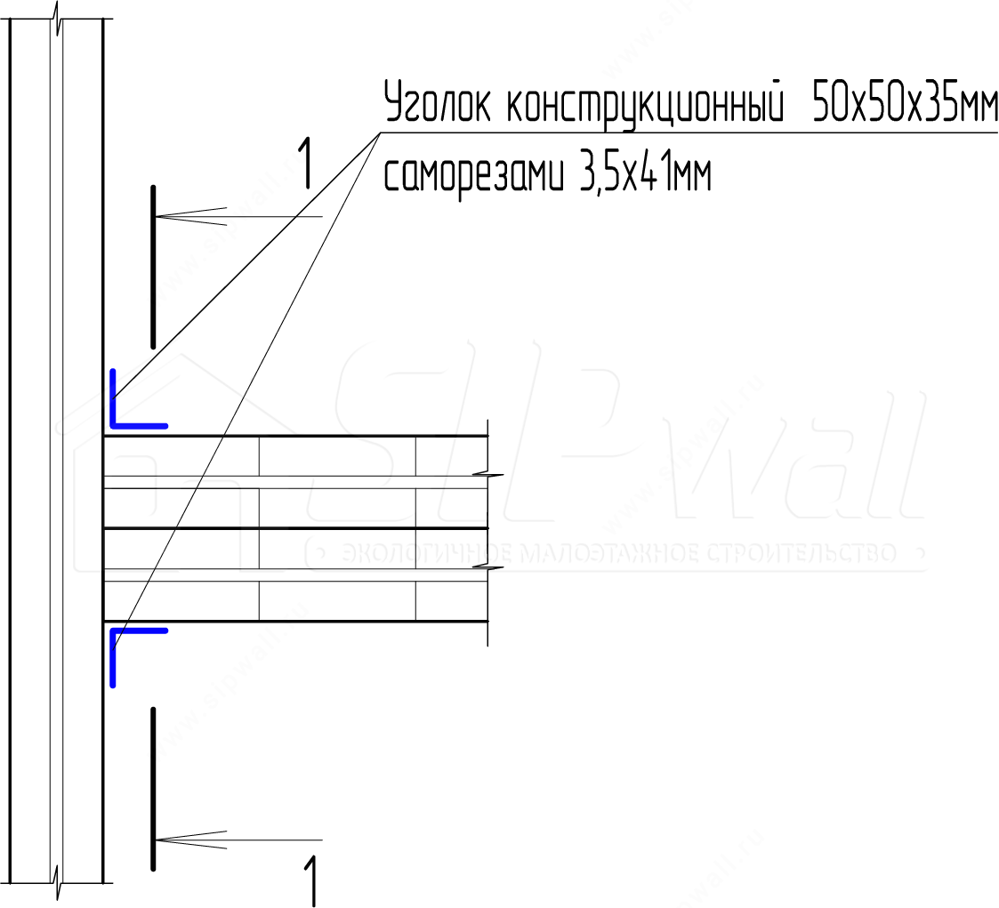
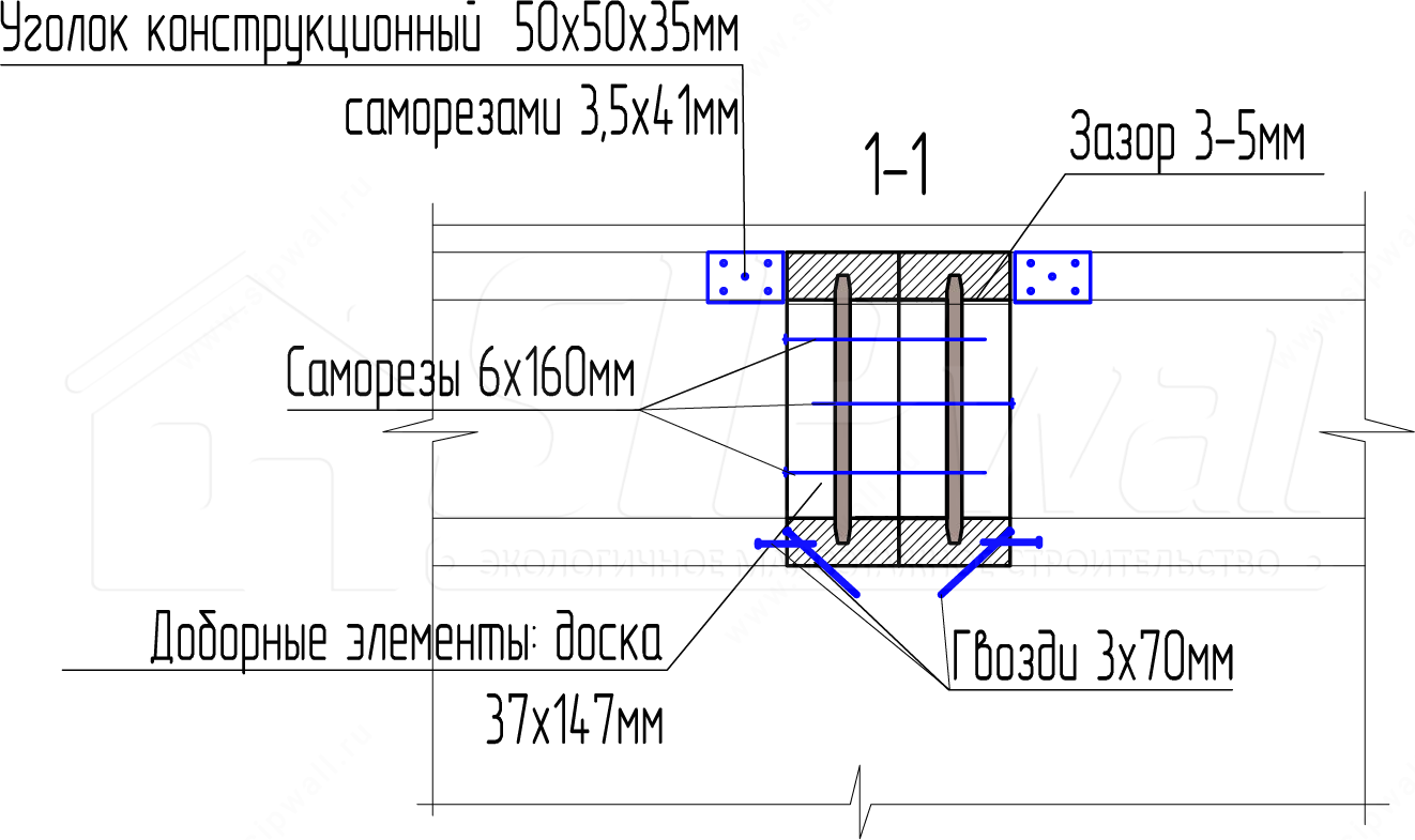
Notes:
1. Reinforce the I-joist header under the post with an extra board 37 × 147 mm, fixing them together with screws 6 × 160 mm, 4-6 pcs. (100 mm spacing).
2. Fix the detail between the top flanges of the I-joist and the I-joist header with structural angles 50 × 50 × 35 mm and screws 3,5 × 41 mm (2 pcs.).
3 Fix the bottom flange with nails 3 × 70 mm to the top strapping timber of the first-floor walls (4 pcs.).
Detail 8
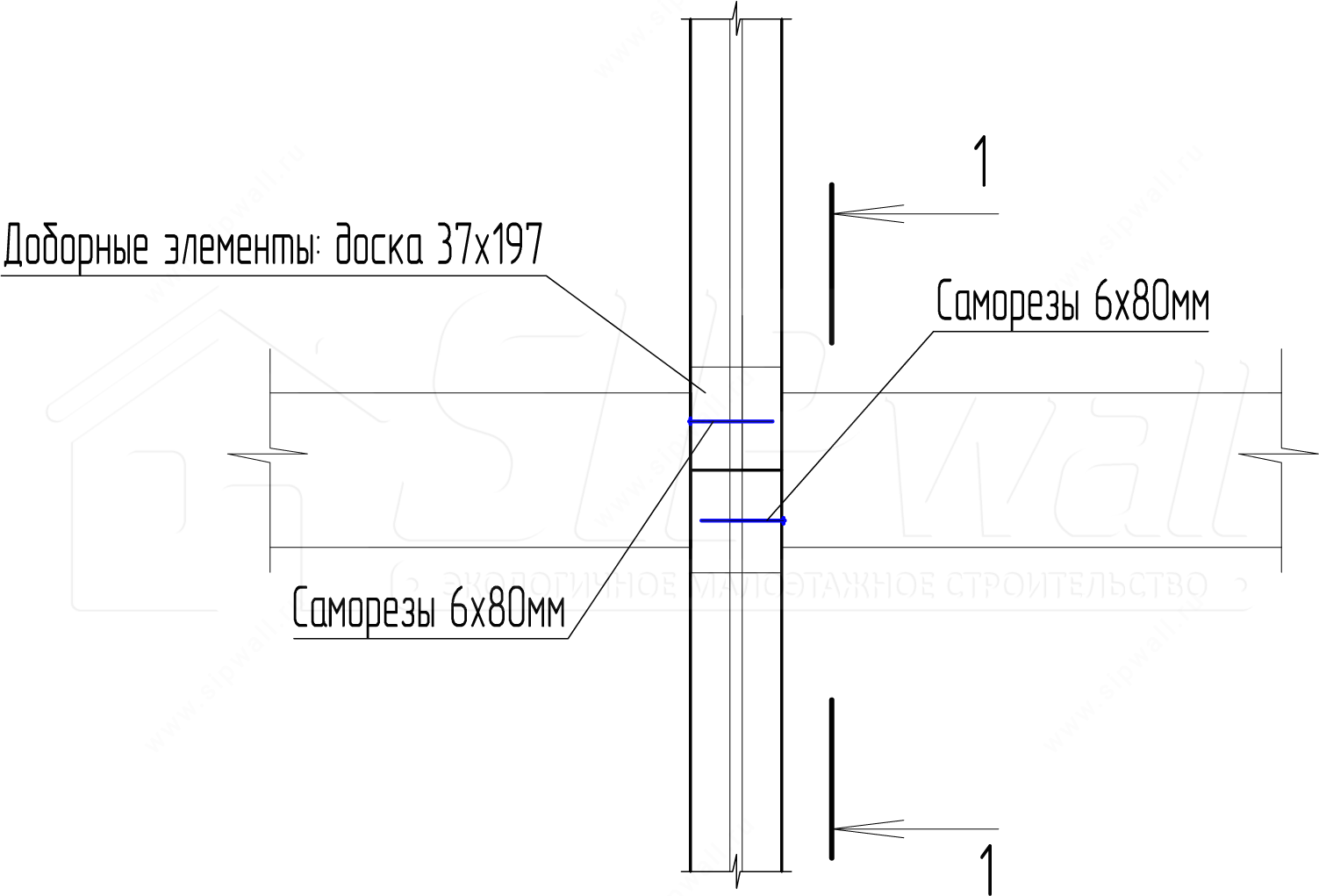
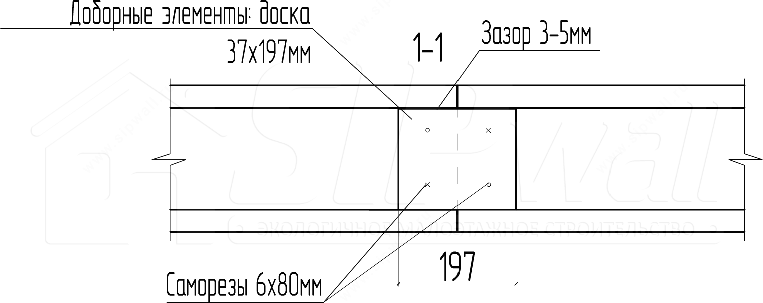
Notes:
1. Join the I-joists to each other along their length at a support using extra board pieces 37 × 197 mm with a 3 mm gap at each flange, with screws 6 × 80 mm, 4-6 pcs. per detail.
2. Fix the I-joists to the top strapping board of the first-floor wall panels with nails 3 × 70 mm, 4 pcs. per bottom flange (2 pcs. into the joist and 2 pcs. into the strapping timber).
Detail 8*
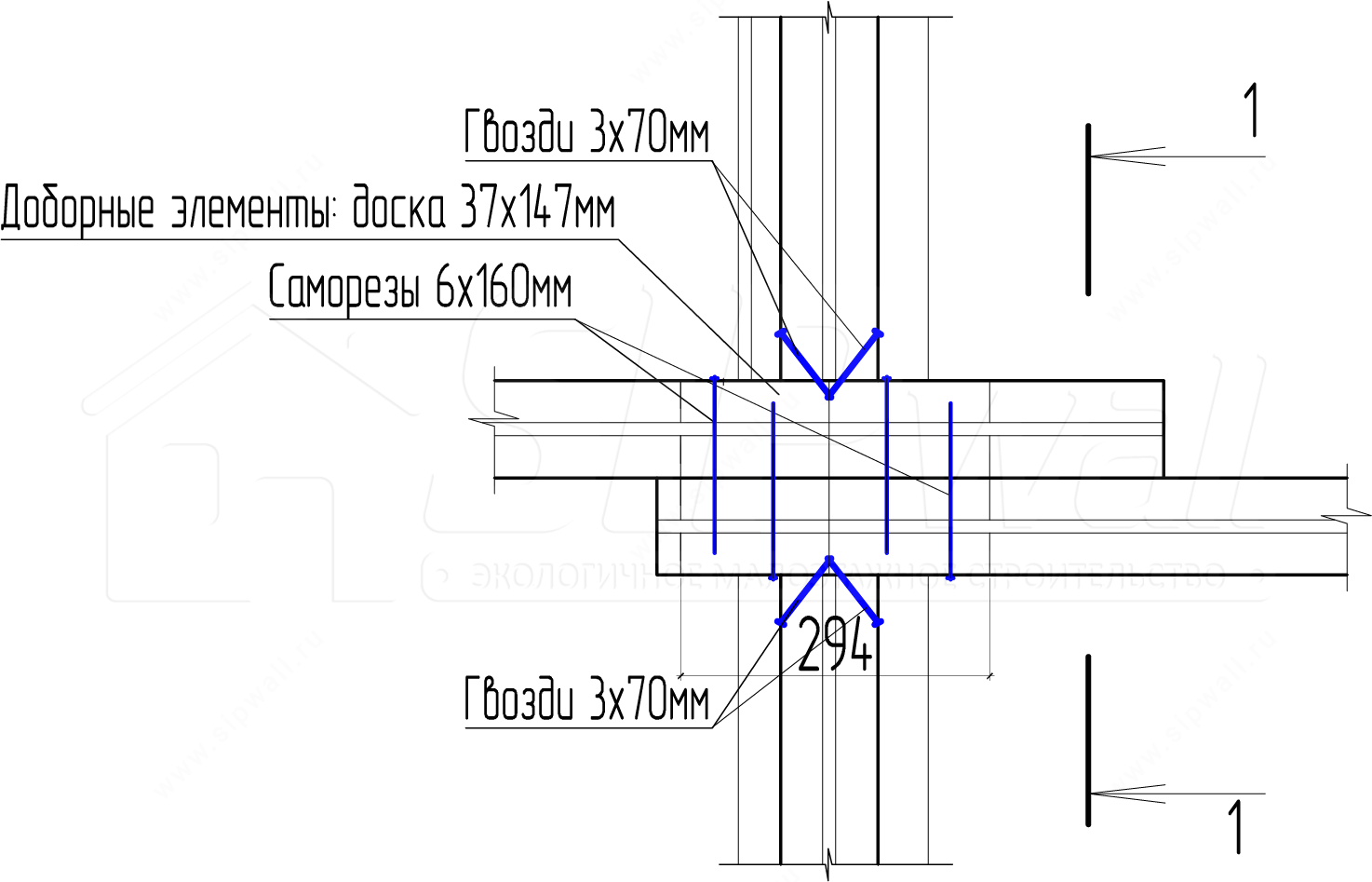
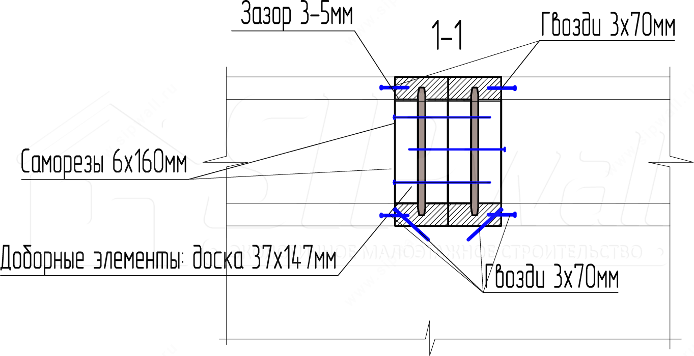
Notes:
1. Join the I-joists to each other along their length at a support using extra board pieces 37 × 147 mm with a 3 mm gap at each flange, with screws 6 × 160 mm, 10-12 pcs. per detail.
2. Fix the I-joists to the top strapping board of the first-floor wall panels with nails 3 × 70 mm, 4 pcs. per bottom flange.
Detail 9 (reinforcing I-joists)
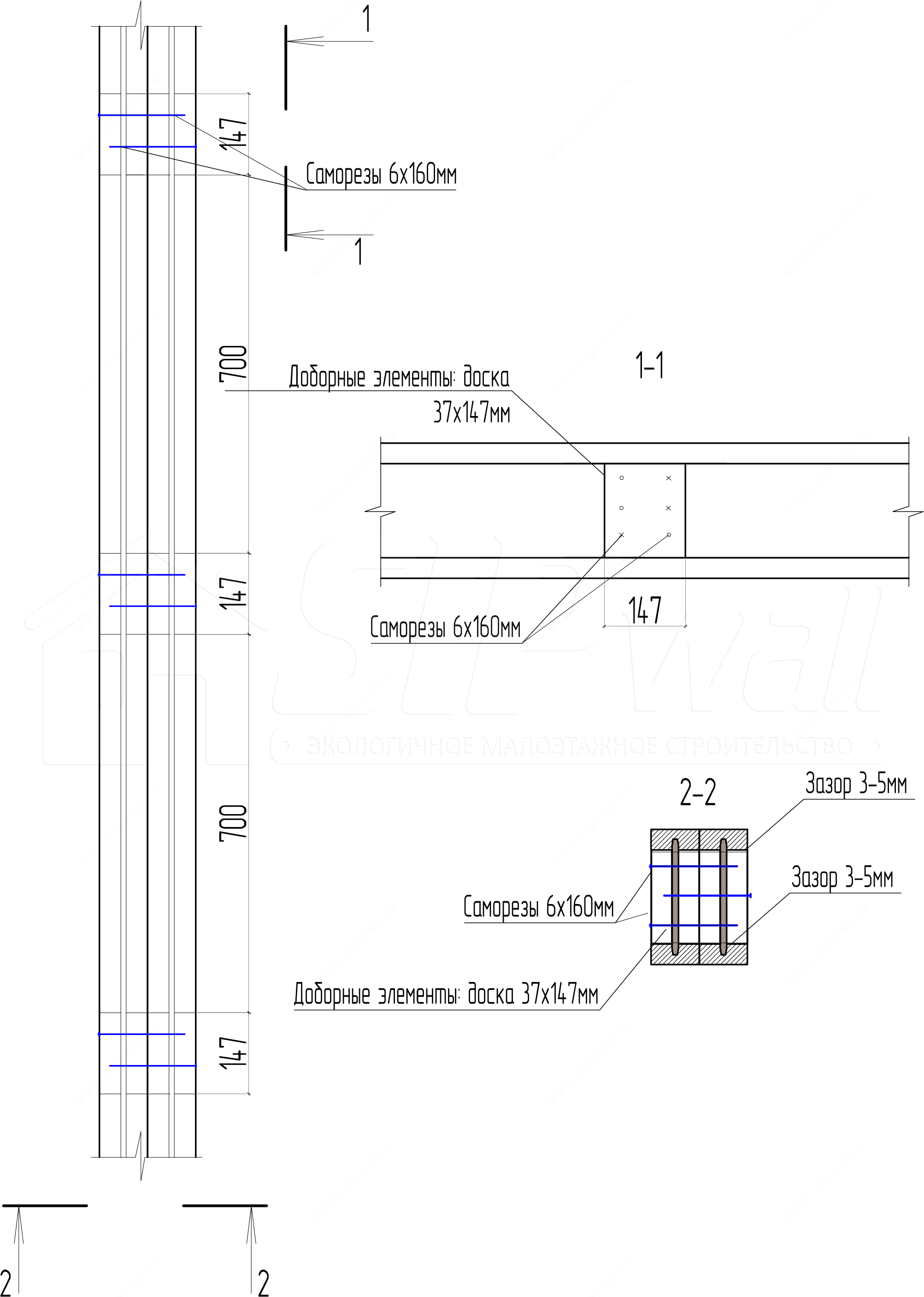
Note:
Join double I-joists to each other (at a spacing of 850 mm) along their length using extra board pieces 37 × 147 mm with a 3 mm gap at each flange, with screws 6 × 160 mm, 4-8 pcs. per detail.
Detail 10
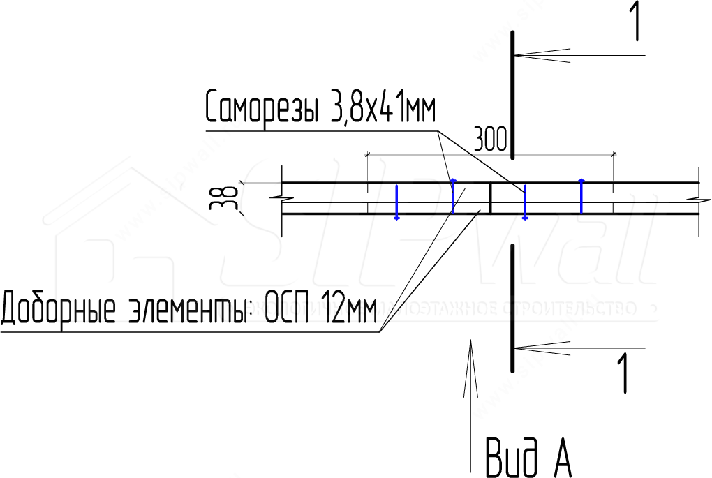
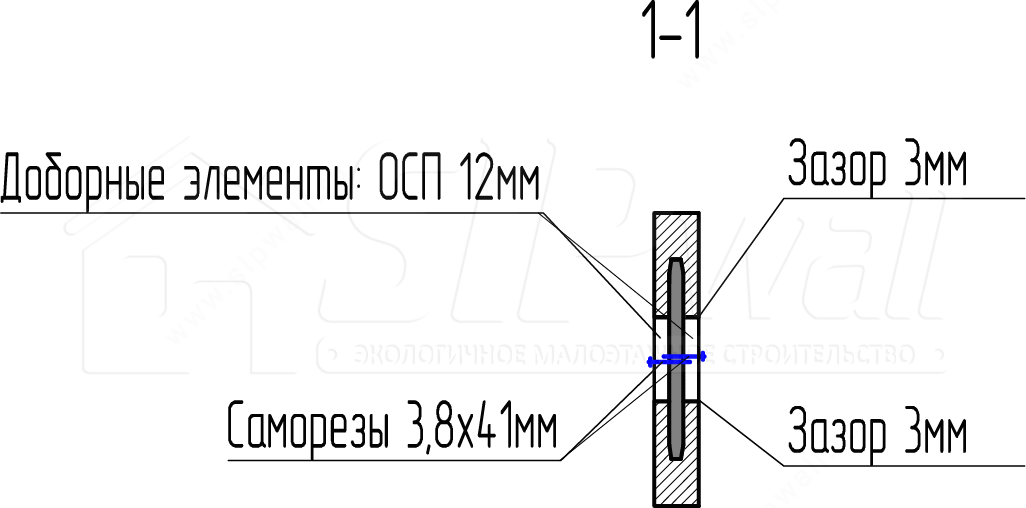
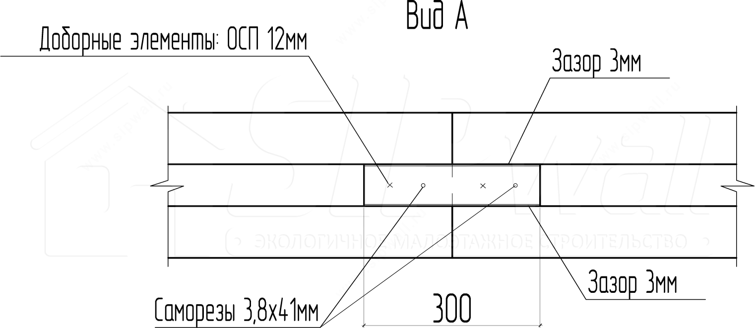
Notes:
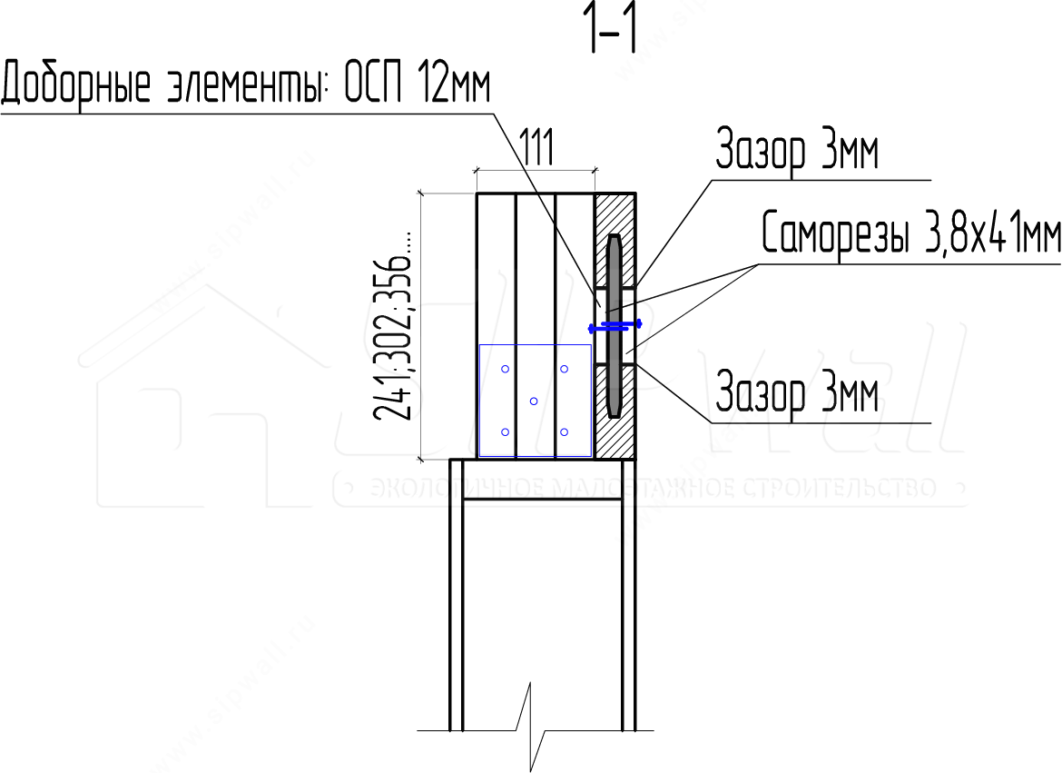
1. Join the I-joist strapping beams to each other along their length using extra OSB pieces 12 mm with a 3 mm gap at each flange, with screws 3,8 × 41 mm, 4-6 pcs. per detail.
2. Fix the I-joist strapping beams to the support as shown in Detail 1.
Detail 11
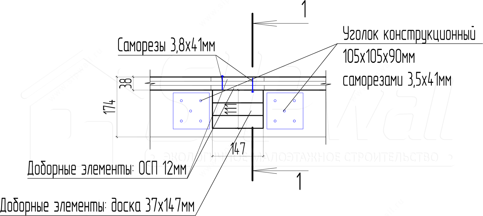
Note:
Build the post base up from three boards 37 × 147 mm with screws 4,2 × 64 mm and fix it to the support with structural angles 105 × 105 × 90 mm and screws 3,5 × 41 mm.
Specification of frame elements and dry lumber for the floor at level +3,063
| № | Name | Thickness, m | Height, m | Element length, m | No. of elements, pcs. | Total board length required, m | Total board length accepted, m | No. of boards, pcs. | V, m³ |
|---|---|---|---|---|---|---|---|---|---|
| 1 | 2Л1 (joist – I-beam) | 0,038 | 0,241 | 6,976 | 2 | 13,952 | – | – | – |
| 2 | 2Л2 (joist – I-beam) | 0,038 | 0,241 | 7,400 | 2 | 14,800 | – | – | – |
| 3 | 2Л3 (joist – I-beam) | 0,038 | 0,241 | 5,500 | 2 | 11,000 | – | – | – |
| 4 | 2Л4 (joist – I-beam) | 0,089 | 0,241 | 6,900 | 10 | 69,000 | – | – | – |
| 5 | 2Л5 (joist – I-beam) | 0,089 | 0,241 | 3,488 | 24 | 83,712 | – | – | – |
| 6 | 2Л6 (joist – I-beam) | 0,089 | 0,241 | 3,531 | 2 | 7,026 | – | – | – |
| 7 | 2Л7 (joist – I-beam) | 0,089 | 0,241 | 2,108 | 5 | 10,540 | – | – | – |
| 8 | 2Л8 (joist – I-beam) | 0,089 | 0,241 | 2,911 | 4 | 11,644 | – | – | – |
| 9 | 2Л9 (joist – I-beam) | 0,089 | 0,241 | 1,656 | 1 | 1,656 | – | – | – |
| 10 | 2Л10 (joist – I-beam) | 0,089 | 0,241 | 1,136 | 1 | 1,136 | – | – | – |
| 11 | 2Л11 (joist – I-beam) | 0,089 | 0,241 | 0,559 | 25 | 13,975 | – | – | – |
| 12 | 2Л12 (joist – I-beam) | 0,089 | 0,241 | 0,536 | 20 | 10,720 | – | – | – |
| 13 | 2Л13 (joist – I-beam) | 0,089 | 0,241 | 0,508 | 3 | 1,524 | – | – | – |
| 14 | 2Л14 (joist – I-beam) | 0,089 | 0,241 | 0,512 | 4 | 2,048 | – | – | – |
| 15 | 2Л15 (joist – I-beam) | 0,089 | 0,241 | 0,409 | 1 | 0,409 | – | – | – |
| 16 | 2Л16 (joist – I-beam) | 0,089 | 0,241 | 0,398 | 1 | 0,398 | – | – | – |
| 17 | 2Л17 (joist – I-beam) | 0,089 | 0,241 | 0,460 | 1 | 0,460 | – | – | – |
| 18 | 2Л18 (joist – I-beam) | 0,089 | 0,241 | 0,313 | 2 | 0,626 | – | – | – |
| 19 | 2Л19 (joist – I-beam) | 0,089 | 0,241 | 0,382 | 1 | 0,382 | – | – | – |
| 20 | Total 89 × 241 | 111 | 255,008 | – | – | – | |||
| 21 | Board for OSB decking joints | 0,037 | 0,1 | – | – | 61,600 | 66 | 11 | 0,2442 |
| 22 | Board for reinforcing I-joists | 0,037 | 0,2 | – | – | 1,000 | 6 | 1 | 0,0444 |
| 23 | Board for reinforcing I-joists | 0,037 | 0,15 | – | – | 1,000 | 6 | 1 | 0,0333 |
| 24 | Total | 0,3219 | |||||||
Specification of OSB for the intermediate floor
| № | Designation | Name | Thickness, m | Width, m | Length, m | Qty, pcs. | S, m² | V, m³ |
|---|---|---|---|---|---|---|---|---|
| 1 | OSB | OSB decking 22 mm | 0,022 | 2,500 | 1,250 | 29 | 90,6250 | 1,9938 |
| 2 | Total | 90,6250 | 1,9938 | |||||
Fastener schedule for the intermediate floor
| № | Name | Qty, unit | Alt. unit |
|---|---|---|---|
| 1 | Fastening angle 50 × 50 × 35 × 2,5 mm (reinforced) | 4 pcs. | – |
| 2 | OBR-Z timber support 25 × 140 × 76 mm (split, left + right = 1 pcs.) | – | – |
| 3 | Wood screws 3,8 × 41 mm | 1590 pcs. | 3,53 kg |
| 4 | Wood screws 6 × 80 mm | 60 pcs. | 0,57 kg |
| 5 | Wood screws 6 × 120 mm | – | – |
| 6 | Wood screws 6 × 160 mm | 20 pcs. | 0,37 kg |
| 7 | Nails 3,8 × 41 mm | 1050 pcs. | 4,55 kg |